


2.10 Preparations Before Start-up
Preparing before start-up uses a check list to powering up the EPS 7000. Reference the EPS 7000 Shared Systems
Users Manual 86-134005-00, and Installation Manual for Single module and Shared Systems 86-134003-00, in
conjunction with this start-up procedure, to utilize information of the controls and indicators during start-up.
2.10.1 Checks Before Start-up
Before starting the EPS 7000, thoroughly read this manual to be certain that you fully understand the operation of
the EPS 7000 Single Modules indicators, controls, and operational sequences.
Before starting the EPS 7000, make certain that these conditions exist (as applicable to your installation):
◗ All power and control wires have been properly connected and securely tightened.
◗ The upstream and downstream protective devices are not tripped, and have been sized properly for the
UPS and load requirements.
◗ The input voltage is the same as indicated on the UPS nameplate, located inside the left door of the EPS
7000 module.
◗ The air filters located inside each EPS 7000 module front door are properly installed and free of dust, dirt,
and debris. Make certain that no objects block the air intake around the front bottom of the enclosures, and
that the air exhaust at the top rear of the enclosures is free of obstructions.
◗ The UPS module input isolation circuit breaker Q1 is in the OFF (open) position.
◗ The bypass circuit breaker Q4S is in the OFF (open) position.
◗ The optional maintenance bypass circuit breaker Q3BP (if present) is in the OFF (open) position.
◗ The optional UPS isolation circuit breaker Q5N (if present) is in the OFF (open) position.
◗ The battery disconnect circuit breaker QF1 is in the OFF (open) position.
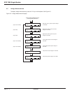
2.10.2 Start-up
The following start-up procedure should be performed during the initial start-up following installation of the system, and
this sequence should be followed any time that the EPS 7000 UPS is being restarted from an off condition (i.e., after
the UPS has been powered down by removing the upstream AC input power and opening all the circuit breakers of
the UPS).
a. Apply power to Q4S by closing the upstream circuit breaker supplying Q4S.
b. Apply power to the UPS input by closing the upstream circuit breaker supplying the main AC input (mains 1).
c. Close the optional maintenance bypass circuit breaker Q3BP (if present). Power is now available at the UPS
output (the load is energized) via the bypass source.
d. Close the control or bypass circuit breaker Q4S. The static switch will come on-line; the fans will start.
e. Close the output isolation circuit breaker Q5N (if present).
f. Open the maintenance bypass circuit breaker Q3BP (if present). The load is now supplied via the bypass
source.
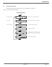
Note that if your UPS configuration does not include the maintenance bypass option, start-up requires only
closing Q4S to supply the bypass source to the attached load.
Operation
EPS 7000 Single Module
page 2 —12