


2.11.1 Emergency Shutdown Using EPO
CAUTION: Pressing the EPO disconnects the attached load. The
emergency power off (EPO) is to be used during emergency
situations only, where a hazard to personnel or equipment
exists, such as during a fire. DO NOT USE THE EPO TO
TURN THE UPS OFF; follow the procedures listed in
this section for turning the inverter on and off.
During an emergency situation, such as a fire in the computer or electrical room, the UPS and all downstream
devices can be instantly shut down by pressing the “emergency power off” (EPO) pushbutton on the front panel of
the UPS cabinet, or by pressing the “remote emergency power off” (REPO) optional pushbutton located within the
room.
The EPO or REPO pushbuttons should not be used for normal shutdown of the equipment; when activated, ground
paths may be broken (depending on installation) and sensitive loads attached to the UPS may lose safety ground
connection.
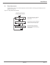
2.11.2 Normal Shutdown
To shut down the UPS, press the “inverter off” pushbutton on the module front panel for 3 seconds. To restart, press
the “inverter on” pushbutton. Note that the transfer will occur only if the inverter is synchronized to the bypass;
otherwise, a forced transfer is needed, see section 2.12 Forced Transfers.
To isolate the UPS for maintenance, or to transfer the load to the bypass AC input source (if present), follow
the procedure that applies to your configuration.
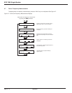
2.11.3 With Maintenance Bypass
This procedure assumes that the UPS is operating normally, with the attached load supplied via the UPS inverter:
1. Stop the inverter by pressing the “inverter off” pushbutton on the UPS front panel for 3 seconds. The audible
alarm will sound; silence the alarm by pressing the audible alarm reset pushbutton on the hidden panel. See
section 1.5 Single Module Indicators and Controls.
If the transfer conditions are not satisfied (bypass out of tolerance or another reason), a forced transfer will be
required., in this case refer to section 2.12 Forced Transfers for procedures.
2. Depress transfer initiate switch. Unlock and remove the key from key interlock. Unlock and close the mainte-
nance bypass circuit breaker Q3BP, see Figure 1-3.
3. Open the UPS isolation circuit breaker Q5N and lock open. The UPS is now isolated from the load which is
supplied by the bypass AC input source.
4. Open the circuit breaker Q4S.
5. Open the battery disconnect circuit breaker(s) QF1.
6. Open the input isolation circuit breaker Q1.
7. Remove the key from Q5N.
8. Insert the key into key interlock and turn to lock. The UPS system is ready for maintenance.
Operation
EPS 7000 Single Module
page 2 —14