


Ø
On/off This pushbutton is reserved for future use.
°
Confirmation/Verify Depending on the displayed message, this pushbutton may serve to indicate confir-
mation, positive response, and other functions.
1.5.2.3 Numbered Lights
During normal operation, the green LED #1 will be on, indicating that the UPS core controller communicates with
the display. If there is an alarm condition, the red LED #1 will turn on.
1.5.3 Hidden Panel Indicators
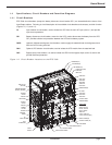
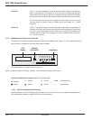
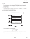
The hidden panel is located behind the hinged cover, at the lowest pane of the front panel, refer to Figure 1-6.
The hidden panel includes the alphanumeric display and controls, and following controls and indicators, see Figure
1-8 and 1-9.
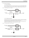
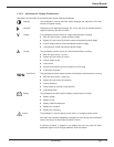
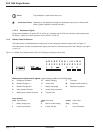
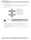
Figure 1-9: Hidden Panel Alphanumeric LEDs and Pushbutton Indicators and Controls.
Hidden panel alphanumeric legend: (upper display, details on following page)
A Emergency Shutdown G Battery charging L Overload
B Rectifier/Charger on H Inverter fault M Bypass outside tolerance
C Rectifier/Charger fault I Battery discharged N Maintenance position
D Input Outside Tolerance J Inverter Desynchronized
F Battery temp. outside Tolerance K Transfer Fault
(lower display)
(port) Test connector fault Clear faults (audio) Alarm reset
1 Battery charge cycle 2 Return to float voltage (key) Security
3 Inverter sync/desync 4 Forced Transfer 5 Forced Shutdown
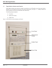
Introduction
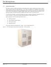
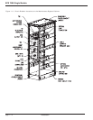
EPS 7000 Single Module
page 1 — 10
NMLKJIHGFEDCBA
12 345
fault