


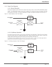
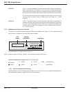
Inverter on (item 6) This green pushbutton is used to start the inverter. When it is pushed, the
green “load protected” LED flashes for three seconds, indicating that the start
command has been received. When the inverter has synchronized with the bypass
AC input (mains 2) source, the static switch transfers the load to the inverter output.
If the inverter cannot synchronize to the bypass AC input (mains 2) source, the load
must be forced to transfer using the hidden panel (see section 2.11, Forced
Transfers).
Inverter off (item 7) This gray pushbutton is used to stop the inverter. When it is pressed for 3
seconds, the inverter stops and the load is transferred to the bypass AC input (mains
2) source. If the uninterrupted transfer conditions are not met, this pushbutton has
no effect and the inverter can be stopped only from the hidden panel (see Section
2.12, Forced Transfers).
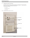
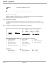
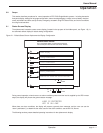
1.5.2 Alphanumeric Display and Controls
The alphanumeric display is located directly below the front panel display. See Figure 1-7. For complete instructions,
refer to section 2.0 Operation, Using the Alphanumeric Displays.
A brief description of the display and controls follow.
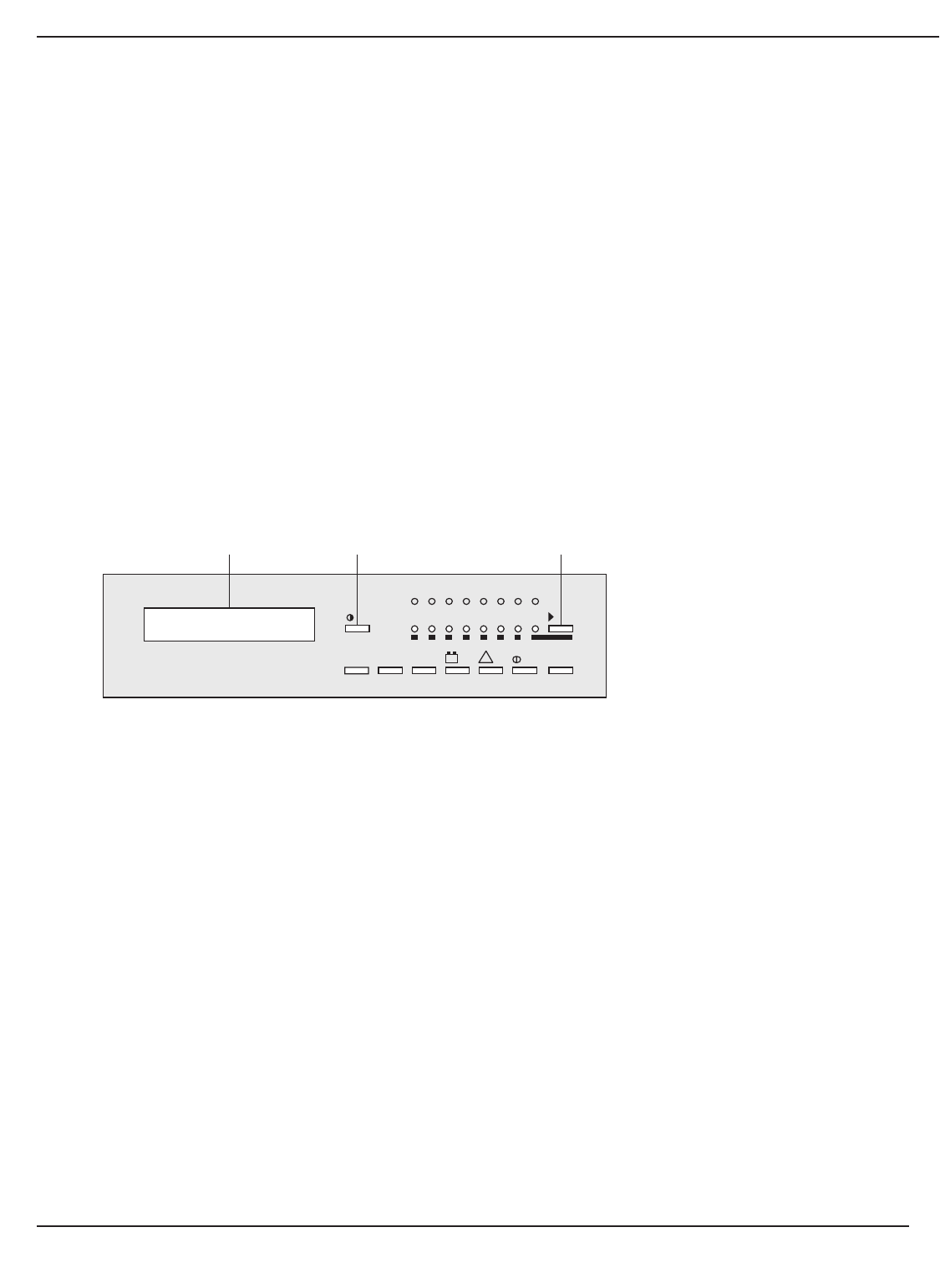
Figure 1-8: Alphanumeric LCD Display , Settings , and Pushbutton Indicators and Controls.
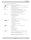
Front Panel Alphanumeric Legend: (details on following page)
ø
Settings
V Voltage A Current W.Hz Power/Frequency
ıı
Battery
⁄⁄
Alarms
ØØ
On/Off
*
Confirm/Verify
1.5.2.1 Two-line Alphanumeric Display
This 40-character, two line LCD displays general status of the UPS continuously, and displays measurements of
UPS operating parameters as selected with the control pushbuttons.
Introduction
EPS 7000 Single Module
page 1 — 8
LCD
display
Settings
pushbutton
˘
pushbutton
87654321
+
–
!
W.HzAV
*
LOAD IS PROTECTED
UPS IS ON LINE