


page 2 —3
Users Manual
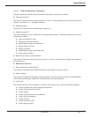
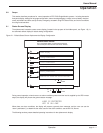
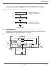
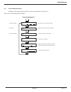
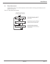
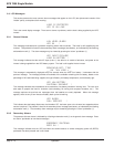
The most serious alarms are stored in the fault log, and may be viewed by following the steps shown in Figure 2-3.
To reset the alarms, press the “clear fault log” pushbutton. See section 1.5.2.2 Alphanumeric Display Pushbuttons.
Figure 2-3: Sequential Alarm Messages for Viewing the Fault Log.
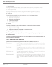
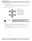
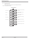
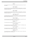
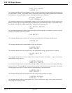
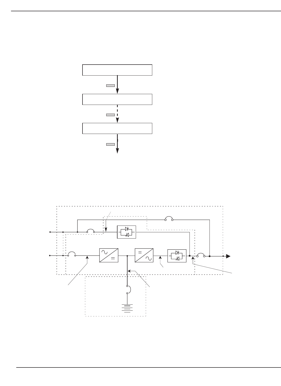
2.4 Sensor Measurements
The LCD displays comprehensive information about UPS performance monitoring functions through sensor measure-
ments devices located within the EPS 7000 single module. See Figure 2-4.
Figure 2-4: Measurement Sensors Located throughout the EPS 7000 Single-Module UPS.
Operation
.
ALARM
. . .
!
⁄
⁄
⁄
(ALARM MESSAGE NUMBER 1)
!
(LAST ALARM MESSAGE)
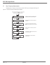
general status screen
This message on the general status screen
indicates an alarm condition. The flashing
exclamation mark ( ! ) indicates that there are
alarm messages to view. To view them, press the
"alarm" pushbutton.
The last alarm message is not followed by an
exclamation mark ( ! ). When the "alarm"
pushbutton is pressed again, the display will
return to the general status screen.
Q1
RECTIFIER/
CHARGER
INVERTER
STATIC SWITCH
Q5N
TO
ATTACHED
LOAD
QF1
BYPASS
AC INPUT/
MAINS 2
MAIN
AC INPUT/
MAINS 1
EPS 8000 UPS MODULE
EPS 8000
BATTERY
CABINET
Q4S or K4S
CHARGER
V, A, Hz
BATTERY
V, A
INVERTER
V, Hz, A, W
LOAD
V, A, Hz, W
BYPASS
V, Hz
Q3BP
EPS 7000 MODULE
BYPASS V, HzMBP
EPS 7000
MODULE