


SMART IP EXTENDER
55
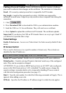
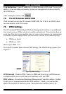
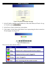
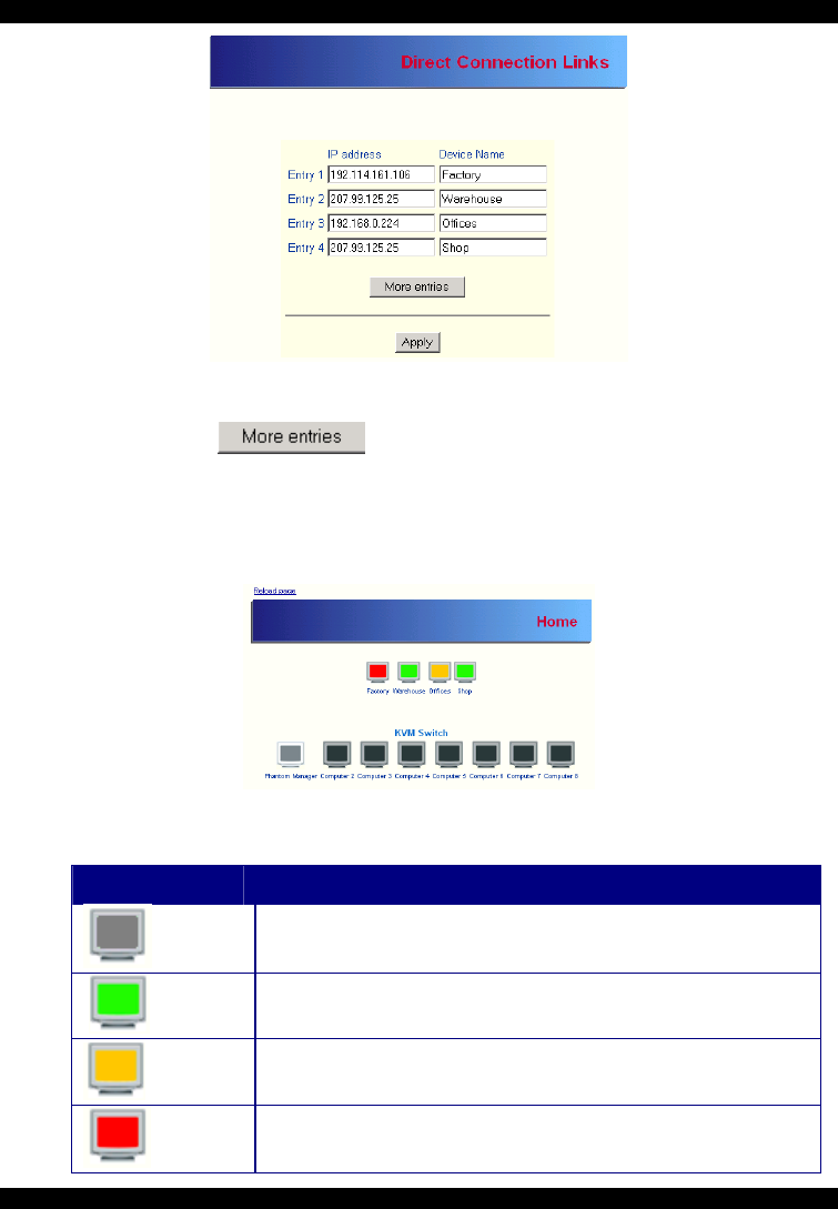
Figure 37 The Direct Connections Links page
3. In the IP address column, type IP addresses of the other Minicom IP units. For up
to 16 entries press
.
4. In the Device Name column type a description.
5. Click Apply. On the Home page Monitor icons representing the direct connection
IP units appear. See Figure 38.
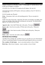
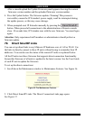
Figure 38 The Monitor icons
The icons are color coded as follows:
Icon Meaning
Gray Powered off or disconnected from the network
Green Powered on but no user is logged in
Orange A user is logged in
Red
User is working with the remote console