


USER GUIDE
8
The table below explains the functions of the front panel LEDs.
LED Function
Activity LED blinks when Network connection is functioning
System OK LED solid when IP Link system connected and functioning
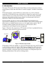
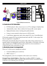
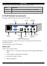
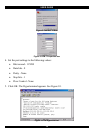
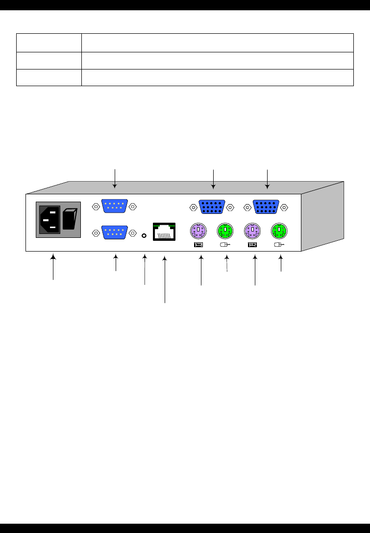
8. The IP Extender rear panel ports
The figure below illustrates the ports on the IP Extender.
Power
connector
POWER
100-240 VAC 50/60 Hz
www.minicom.com
I
0
Keyboard
Mouse
Monitor
Computer
Keyboard port
Computer
Mouse port
Computer
Video card
SERIAL 2
SERIAL 1
USER COMPUTER
Serial 1
Serial 2
ETHERNET
RST
Ethernet
Reset
Figure 4 IP Extender ports
You can work locally on the host system by connecting a KVM console to IP
Extender rear panel.
The Reset button resets the IP Extender.
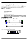
Serial 1 port
Serial 1 port is used as follows:
• IPMI Version 1.5 connection to the remote system using the IPMI Option
cable
• Serial output for modem dial in connection
• Serial pass-through via Telnet
• Initial configuration