


7 - 11
7.2 Program for Refresh and for Receiving LRDP/LWTP Instruction
7
PROGRAMMING
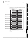
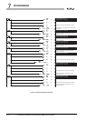
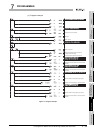
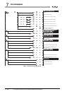
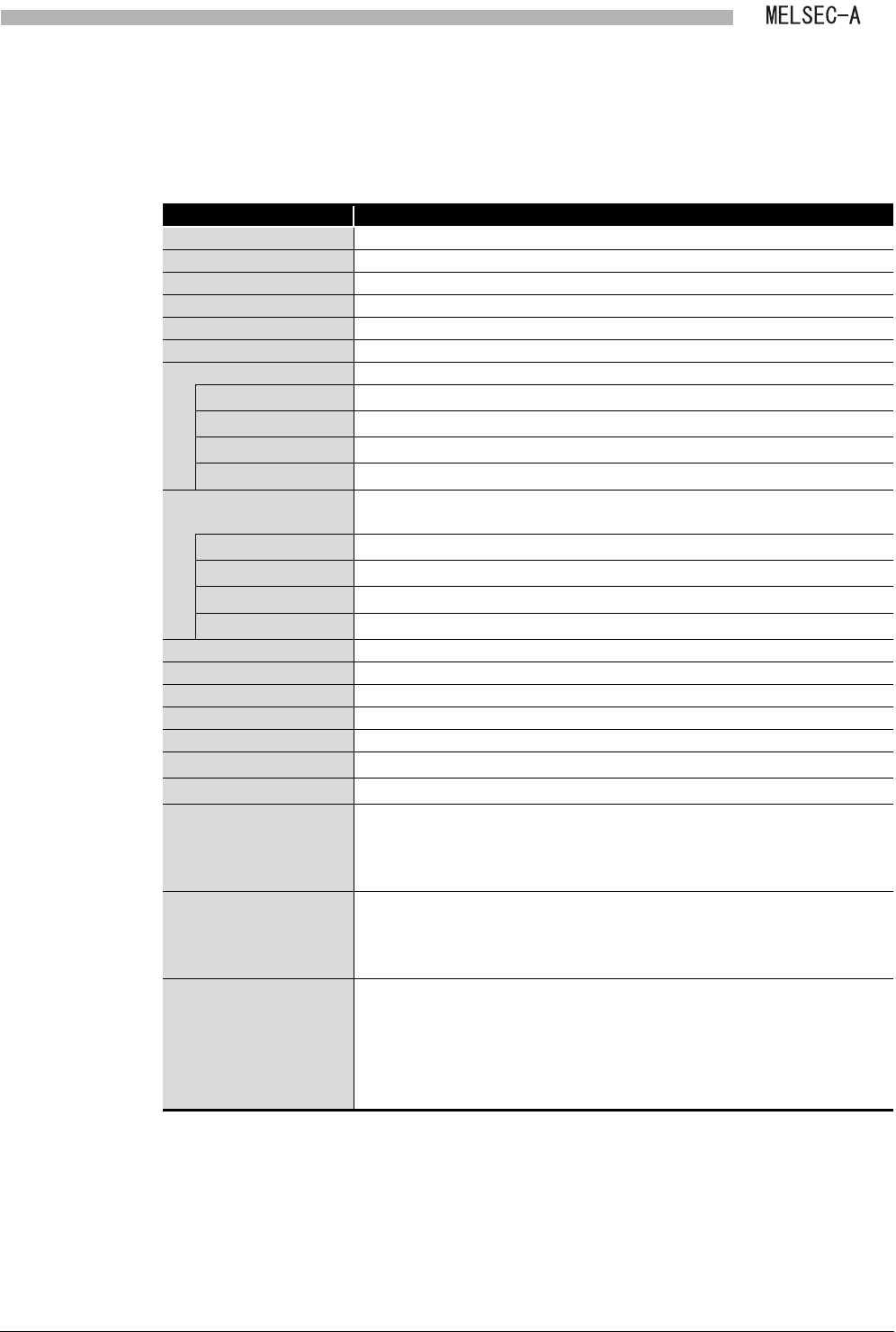
(b) Device list
Devices used in the program are shown.
Note that the local module is mounted in the position indicated as I/O No. X/Y200
to X/Y21F.
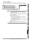
* 1 The range of device use varies depending on the link parameters of the master station.
* 2 The range of device use varies depending on the start devices and the points that are specified by
the LRDP/LWTP instruction of the master station.
* 3 Can be replaced with other devices as necessary.
However, to avoid wrong replacements, we recommend using the program examples described in
the manual without changes.
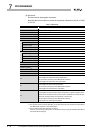
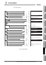
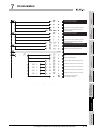
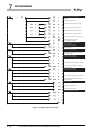
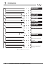
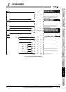
Table 7.3 Device list
Device Description
X200 Link status
X201 B/W initial value setting status
X207 Refresh ready status
Y210 CPU operating status
Y211 Refresh in execution
Y216 Refresh request
Link data -
X1000 to X17FF
*1
Input
Y1000 to Y17FF
*1
Output
B0 to BFFF
*1
Link relay
W0 to WFFF
*1
Link register
LRDP/LWTP instruction
target
-
T0 to T2047
*2
Timer
C0 to C1023
*2
Counter
D0 to D6144
*2
Data register
W0 to WFFF
*2
Link register
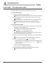
W1002 to W1027 Save area for refresh information table (Not protect device values.)
SM400 Always ON
SM402 After RUN, ON for 1 scan only
SM1240 to SM1255 Special relay (for link) (M9240 to M9255)
SD1243 to SD1255 Special register (for link) (D9243 to D9255)
SD2040 to SD2041
*3
Presence or absence of refresh information table (Protects device values.)
SD2042 to SD2044
*3
Z0 to Z2 save area (Protects device values.)
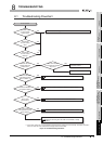
Z0
•When link data are sent/received
Index register for device start number specification
•On the receive processing of the LRDP/LWTP instruction
Index register for start device name specification
Z1
•When link data are sent/received
Index register for device points specification
•On the receive processing of the LRDP/LWTP instruction
Index register for start device No. specification
Z2
•When link data are sent/received
Index register for bit device start number specification (a register equivalent to Z0,
whose unit is converted from bit to word for index modification in link data storage
area when the start number of the bit device is stored in Z0)
•On the receive processing of the LRDP/LWTP instruction
Index register for data length specification