


7
PROGRAMMING
7.2 Program for Refresh and for Receiving LRDP/LWTP Instruction
7 - 14
1
OVERVIEW
2
SYSTEM
CONFIGURATION
3
SPECIFICATIONS
4
FUNCTIONS
5
PREPARATORY
PROCEDURES BEFORE
OPERATION
6
LINK DATA SEND/
RECEIVE PROCESSING
AND PROCESSING TIME
7
PROGRAMMING
8
TROUBLESHOOTING
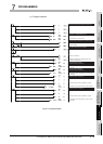
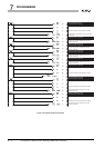
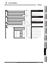
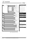
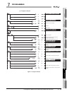
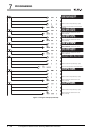
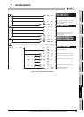
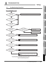
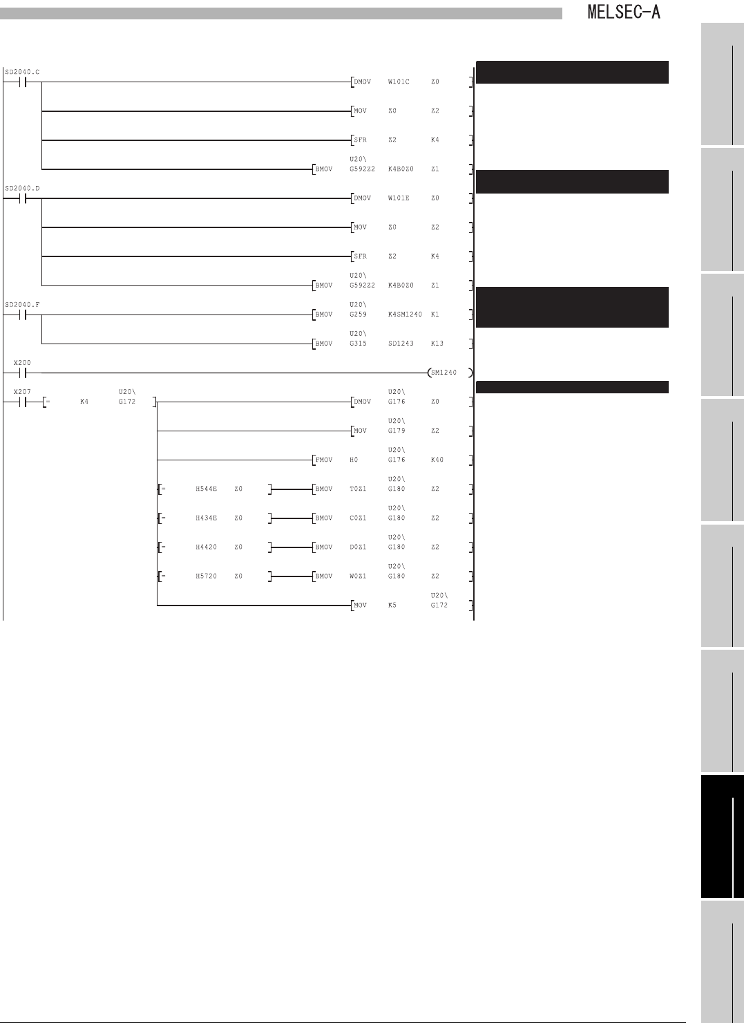
Figure 7.13 Program example (Continued)
B device reception 1 (Latter half): B device reception 1 (Latter half):
Start No. = Z0, No. of words = Z1Start No. = Z0, No. of words = Z1
Obtains B of the other stations from the local
module. (Latter half)
Divides the buffer memory address by 16 (bits).
B device reception 2 (Latter half): B device reception 2 (Latter half):
Start No. = Z0, No. of words = Z1Start No. = Z0, No. of words = Z1
Obtains B of the other stations from the local
module. (Latter half)
Divides the buffer memory address by 16 (bits).
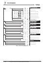
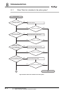
Obtains data of the special register (for link).
LRDP instruction receive processingLRDP instruction receive processing
Obtains the read start device name and start
device No.
Clears the LRDP instruction work area to zero.
Transfers data of the special relay (for link) Transfers data of the special relay (for link)
(from M9240) to the area starting from SM1240.(from M9240) to the area starting from SM1240.
Transfers data of the special register (for link) Transfers data of the special register (for link)
(from D9243) to the area starting from SD1243.(from D9243) to the area starting from SD1243.
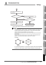
Obtains data of the special relay (for link).
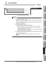
Obtains the read data length.
Transfers the T device value to the work area.
Transfers the C device value to the work area.
Transfers the D device value to the work area.
Transfers the W device value to the work area.
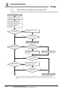
LRDP instruction receive request
(5 = Processing completion)