


3 - 27
3.6 Details of Buffer Memory
3.6.8 Input (X0 to X7FF) and output (Y0 to Y7FF)
3
SPECIFICATIONS
3.6.8 Input (X0 to X7FF) and output (Y0 to Y7FF)
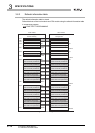
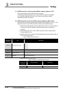
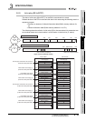
Data of input (X0 to X7FF) and output (Y0 to Y7FF) of X/Y communication is stored.
Refresh devices of the CPU module and the data in this area using the following area in a
sequence program.
• Presence or absence of refresh information table (Buffer memory address: 0
H,
1
H)
• Refresh information table (Buffer memory address: 2
H to 27H)
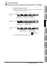
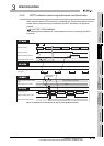
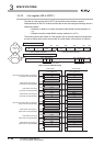
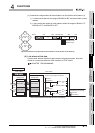
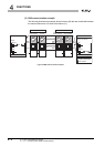
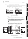
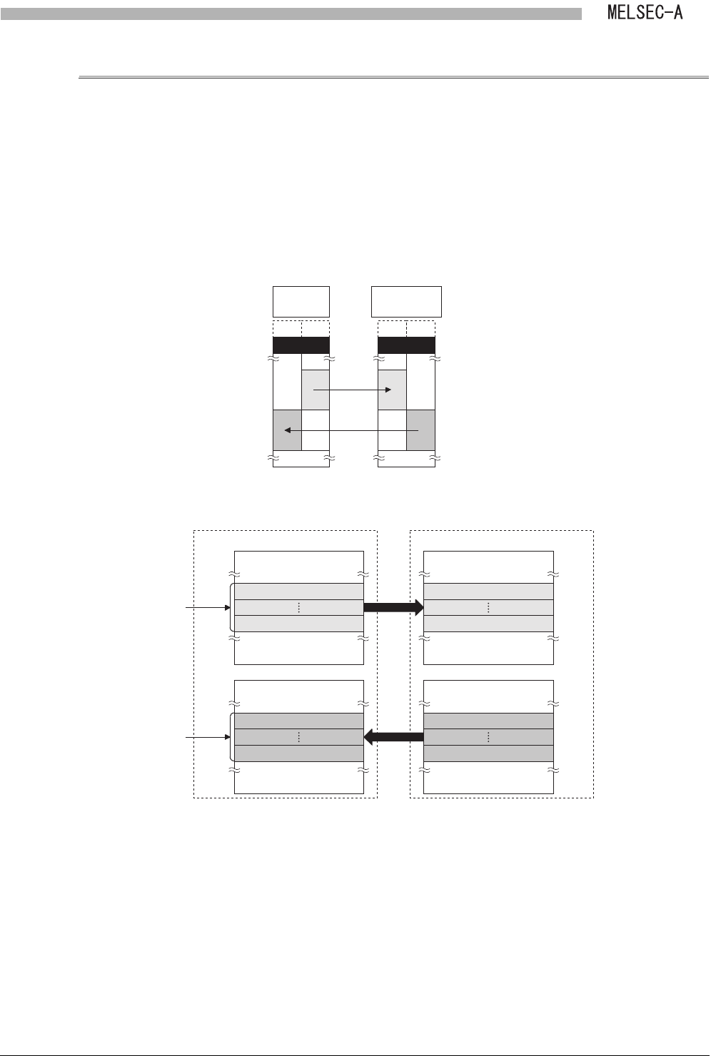
The following shows the refresh of input (X) and output (Y) when link parameters are set
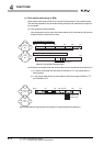
as follows:
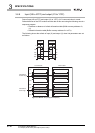
Figure 3.14 Link parameter setting
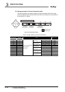
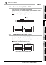
Figure 3.15 Refresh of input (X) and output (Y)
Actual I/OActual I/O
Master
station
0
47
F
400
Q series
local station
XY
0
400
Actual I/OActual I/O
XY
47
F
480
4FF
480
4FF
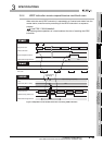
Local module CPU module
Input (X) Input (X)
150
H
190
H
197
H
1CF
H
Output (Y)
1D0
H
218
H
21F
H
24F
H
Output (Y)
X400 to X40F
Host station
receive range
Y480 to Y48F
Host station
send range
X470 to X47F
X400 to X40F
X470 to X47F
Y4F0 to Y4FF
Y480 to Y48F
Y4F0 to Y4FF