


3 - 29
3.6 Details of Buffer Memory
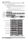
3.6.10 Link register (W0 to WFFF)
3
SPECIFICATIONS
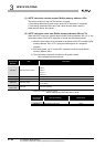
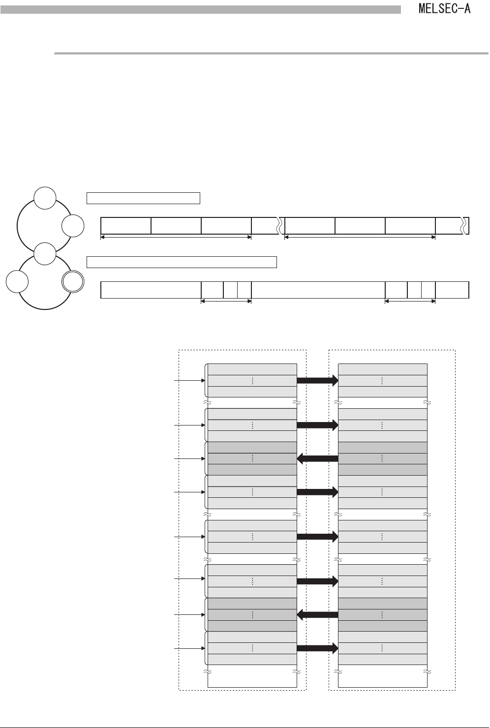
3.6.10 Link register (W0 to WFFF)
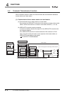
The data of a link register (W0 to WFFF) for the B/W communication is stored.
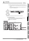
Refresh devices of the CPU module and the data in this area using the following area in a
sequence program.
• Presence or absence of refresh information table (Buffer memory address: 0
H,
1
H)
• Refresh information table (Buffer memory address: 2
H to 27H)
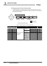
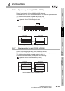
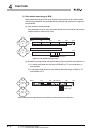
The following shows the refresh of a link register (W) for the case where link parameters
are set as shown below and a local module is a local station in the third tier (l1 station).
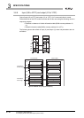
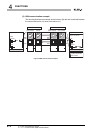
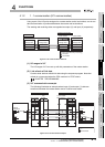
Figure 3.18 Link parameter setting
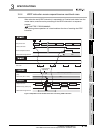
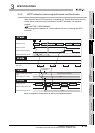
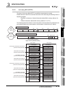
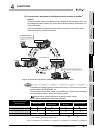
Figure 3.19 Refresh of link register (W)
Link parameters of second tier
ML1
100 200
L2/ m
300 400
200
L2/m
300
l1
280
l2
2C0
M
L1
Second
tier
l1l2
Third tier
L2/m
B/W 0
ML1
L2/m
500 600 700 FFF
(Empty)(Empty)
600
L2/m
700
l1
680
l2
6C0B/W 0 FFF
Link parameters of master station for third tier (L2/m)
First half of link parameters Latter half of link parameters
First half of link parameters Latter half of link parameters
W200
W27F
Local module CPU module
Other station send range (1)
(First half of link parameters)
Send range of master station for second tier
(First half of link parameters)
Host station send range
(First half of link parameters)
Other station send range (2)
(First half of link parameters)
Other station send range (1)
(Latter half of link parameters)
Send range of master station for second tier
(Latter half of link parameters)
Host station send range
(Latter half of link parameters)
Other station send range (2)
(Latter half of link parameters)
Link register (W) Link register (W)
400
H
4FFH
600H
6FFH
800H
8FFH
A00H
67FH
680H
6BFH
6C0H
A7FH
A80H
ABFH
AC0H
13FFH
W0
WFF
W280
W2BF
W2C0
W2FF
W600
W67F
W400
W4FF
W680
W6BF
W6C0
W6FFAFF
H
W200
W27F
W0
WFF
W280
W2BF
W2C0
W2FF
W600
W67F
W400
W4FF
W680
W6BF
W6C0
W6FF