


7
PROGRAMMING
7.1 System Configuration and Setting Conditions
7 - 2
1
OVERVIEW
2
SYSTEM
CONFIGURATION
3
SPECIFICATIONS
4
FUNCTIONS
5
PREPARATORY
PROCEDURES BEFORE
OPERATION
6
LINK DATA SEND/
RECEIVE PROCESSING
AND PROCESSING TIME
7
PROGRAMMING
8
TROUBLESHOOTING
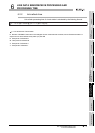
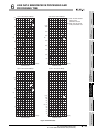
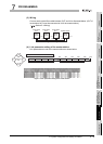
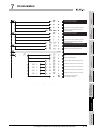
(3) Wiring
Connect each optical fiber cable between OUT and IN as illustrated below. (OUT of
local station No.3 must be connected to IN of the master station.)
( Section 5.4 Wiring)
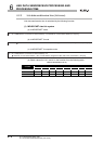
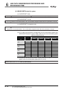
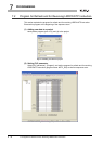
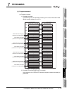
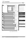
(4) Link parameter setting of the master station
Link parameters are set to the master station as shown below.
Figure 7.2 Wiring
Figure 7.3 Link parameter setting of the master station
Master station
Station
No.00
OUT IN
Local station
No.1
Station
No.01
Station
No.02
OUT IN
Front
OUT IN
Front Front
Local station
No.2
Station
No.03
OUT IN
Front
Local station
No.3
Link parameters for second tier
M
200
(Empty)
400
M
L1
Second
tier
L2
B/W 0 FFF
(Empty)
First half of link parameters
L3 L1 L2 L3
10080 180
M
600
Latter half of link parameters
L1 L2 L3
500480 580