


5 - 11
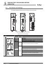
5.4 Wiring
5.4.3 Shielded twisted pair cable
5
PREPARATORY PROCEDURES BEFORE
OPERATION
5.4.3 Shielded twisted pair cable
The following describes how to connect a shielded twisted pair cable with the local
module.
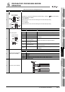
(1) Precautions for wiring
(a) Laying shielded twisted pair cable
When laying a shielded twisted pair cable, pay attention to the following points so
that it will not be affected by noise or surge induction.
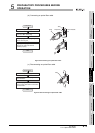
1) Do not install a shielded twisted pair cable together with the main circuit, high-
voltage cable, or load line, and also do not bring them closer to each other.
(Keep a distance of 100mm (3.94 inch) or more between them.)
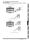
2) Do not use a part of shielded twisted pair cable (for example, one pair among
three pairs) as a cable for power supply.
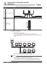
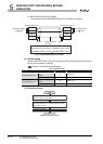
(b) Connection of terminating resistor
For the stations at both ends of the MELSECNET/B data link system, connect
SDA/RDA and SDB/RDB with an attached terminating resistor (110 , 1/2W).
(Refer to (2) in this section)
(c) Connecting/disconnecting a shielded twisted pair cable
Be sure to shut off all phases of the external power supply used by the system.
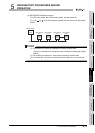
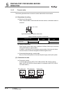
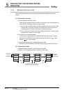
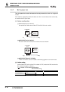
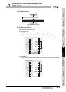
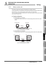
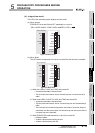
(2) Connection of cable
A shielded twisted pair cable is connected as shown below.
In addition, use a terminating resistor for stations at both ends.
Figure 5.12 Connection method
SDA/RDA
SDB/RDB
SG(L)
FG
SDA/RDA
SDB/RDB
SG(L)
FG
SDA/RDA
SDB/RDB
SG(L)
FG
SDA/RDA
SDB/RDB
SG(L)
FG
Shielded twisted pair cable
Terminating
resistor
(110 1/2W)
Terminating
resistor
(110 1/2W)