


MRV Communications, Inc. – Installation Manual
12
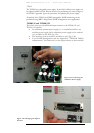
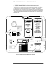
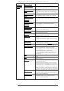
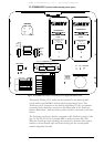
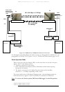
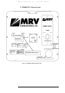
Selectors
(DIP Switch
DS1 Toggles)
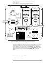
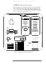
---shown on
Figures 1.5and
1.6
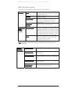
Data Rate
(Toggles 1, 2, 3 and
4)
Set the transmission rate of the transceiver (internal
clock).
- Fast Ethernet: 1,2,3,4 OFF
- ATM/OC3/STM1: 155 Mbps: 2,3,4 OFF, 1 ON
- SMPTE 143 Mbps: 3,4 OFF, 1,2 ON
- E3: 34.368 Mbps 1,2,4 OFF, 3 ON
- T3: 44.736 Mbps: 2,4 OFF, 1,3 ON
- OC1/STM0: 51.840 Mbps: 1,4 OFF, 2,3 ON
- Customized 1 : 4 OFF, 1,2,3 ON
- Customized 2 : 1,3,4 OFF, 2 ON
- Open Protocol: 1, 2, 3 OFF, 4 ON.
Mode Select
(Toggles 1, 2)
Set the Operating Mode
ALIGNMENT = Idle transmitted automatically
NORMAL
= Signal received via the F/O port is
transmitted through the Airlink TX. Signal received
via the Airlink RX is transmitted through the F/O
TX.
LOOPBACK
= Data received by the F/O RX is
directly returned through the F/O TX.
REMOTE LOOP
= Loops the electrical RX to the
electrical TX and optical RX to the optical TX of the
remote unit.
Alignment Signal
Attenuation
(Toggle 3)
ATTENUATION: The alignment signal is
attenuated (~20db) when the DIP switch toggle #3
is moved to ON position.(to use when the
installation distance is less than 900m only for
alignment mode). Switch back to OFF position for
normal mode.
Laser Status
(Toggle 4)
Turning off TXs lasers when the DIP switch toggle
#4 is moved to ON
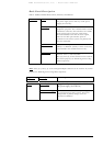
Fusion
(Toggle 5)
This switch toggle enables working with MRV’s
Fusion system (Built-in fusion option or switch
option). For additional information, see page 14.
Switch toggle 5 OFF: Fusion not Active (Disabled)
Switch toggle 5 ON: Fusion active (Enabled).
Window Heater
(Optional)
(Toggle 6)
Used only with the heating option (To be specified
in the PO).
Switch toggle 6 OFF: The heater is disabled
Switch toggle 5 ON: The heater is enabled.
The heating will start operating only if one of the
following conditions is present: or the temperature is
lower than 15
o
C; or the humidity level in the air is
above 80%. There is a controller with a thermostat
inside the TereScope, which controls the heating in
accordance with the above conditions.
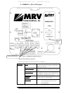
IP address set up
(Toggle 8)
When the Switch toggle is on OFF position, the
TereScope’s IP address is the default one (shown on
the back panel label: 10.0.0.101). To set a new IP
address, please refer to the “IP address setting
procedure for TereScope management card” file in
the Manuals CD. The new IP address is valid only
after the TereScope is powered off and on.
Selectors
(DIP Switch
DS2 Toggles)
-- shown in
Figures 1.5 and
1.6
Control Mode
(Toggle 10)
When the Dip Switch toggle #10 is on OFF
position, the TereScope is in the HARDWARE
mode, i.e. the TereScope is controlled only by the
TereScope itself by means of the switches on its
back panel.
When the Dip Switch toggle is on ON position, the
TereScope is in the SOFTWARE mode i.e. the
TereScope is controlled by the management
Software and various functions can be activated by
means of this management Software.