


MRV Communications, Inc. – Installation Manual
20
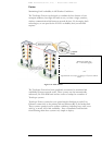
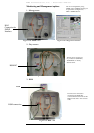
AirLink Flag Green LED indicates that a signal is received by the
Airlink receiver. Switches ON at the threshold
level.
Airlink Sync Yellow LED indicates that the air signal received
from the opposite side is synchronized with the
local transceiver. LED switches ON when two
transceivers are synchronized.
Tributary Link LEDs 4 yellow LEDs. Every LED indicates a signal is
received by the electrical interface in its channel.
LED switches ON when an outside signal is
received.
The channels are numbered from A to D.
Indicators
(7-segment
display, LEDs)
Optical Power
Digital readout indicates in mV the Optical Power
level received by the Airlink receiver
Selectors
(Upper DIP
Switch
Toggles) --
shown on
Figure 1.9
IP address set up When the Switch toggle is on OFF position, the
TereScope’s IP address is the default one (shown
on the back panel label: 10.0.0.101). To set a new
IP address, please refer to the “IP address setting
procedure for TereScope management card” file in
the Manuals CD. The new IP address is valid only
after the TereScope is powered off and on.
Line coding
(Toggle No 1)
Use to select the Coding mode:
AMI or HDB3 for E1 or B8ZS for T1.
Receive
Sensitivity
(Toggle No 2)
Use to select Long Haul or Short Haul. Depends
on the length of the used cable: For the length of
less than 200 m, select Short Haul, for the length
over 200m, select Long Haul.
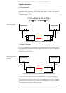
Mode of Operation
(Toggles 3& 4)
Sets the Operating mode:
LOCAL LOOP = Loops the electrical RX to the
electrical TX and Optical RX to the optical TX
REMOTE LOOP =Loops the electrical RX to
the electrical TX and optical RX to the optical TX
of the remote unit.
NORMAL = Signal received through the electrical
RX is transmitted through the Airlink TX to
opposite RX. Signal received through Airlink RX is
transmitted through the electrical TX (Normal =
3& 4 OFF).
Selectors
(Lower DIP
Switch Toggles
A to D) --
shown on
Figure 1.9
(All DIP switch
toggles A to D
can be set
separately.)
Impedance
(Toggle 5)
Used to match the cable impedance.
For E1 75R or T1 100R – ON position
For E1 120R – OFF position
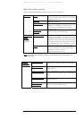
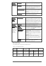
Dip switch setting
Every DIP switch is set up for the channel above it.
Table 6: Lower Dip Switches Setting
Switch
Position
Line coding Receive
Sensitivity
Operation Mode Impedance
1 2 3 4 5
ON AMI Long Haul
Local
Loopback
Remote
Loopback
E1: 75 Ω
T1: 100 Ω
OFF
E1: HDB3
T1: B8ZS
T1: Limited LH
E1: Short Haul
Normal Normal
E1: 120 Ω