


MRV Communications, Inc. – Installation Manual
47
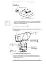
Transceiver Alignment
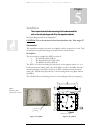
Successful installation of the TereScope depends primarily on precise and accurate optical
alignment. Carefully follow the instructions below!!!
Important: Handle the Telescope with great care since it is the main tool for fine
alignment.
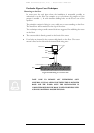
Turn on the power to the TS5000 heads from the power source.
Models G and G-F: Set DIP switch toggles 1,2 to the “Alignment” position (indicated on
the back panel).
Models 155 and 155-F: Set DIP switch toggles 1,2 to the “Alignment” position (indicated
on the back panel). If the installation distance is less than 900m it's recommended to
attenuate the signal for the alignment process, by pushing to ON position the toggle #3 of
dip-switch DS2. Caution: Switch back to OFF position for normal mode operation.
Models ETH and 4U1: Even if the data port is left unconnected, the TS5000 transmits
an Idle Signal which can be used to perform alignment.
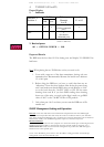
The ttransceiver alignment procedure is implemented in two stages:
− Coarse Alignment
− Fine Alignment
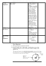
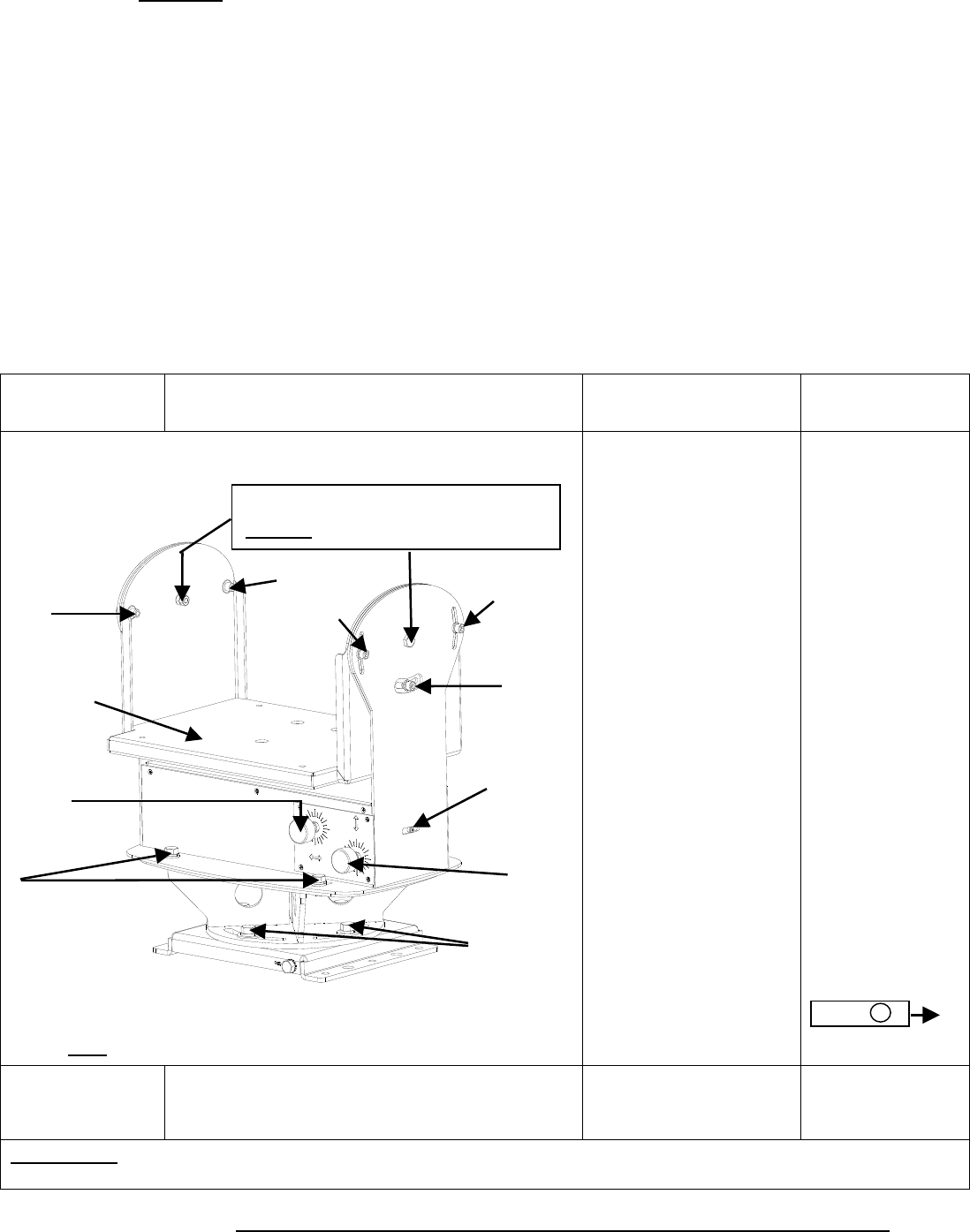
Action Screws Position
Description Notes
1. Coarse
Alignment
All the screws are open (J, L, E, D)
Rotate the transceiver
left and right, up and
down holding it by the
box and looking
through the telescope
till you can see the
opposite site. If the D
screws prevent further
rotation, screws D can
be reassembled in the
nearby holes.
If it is difficult to see
the opposite site due to
the distance or haze,
make sure at this stage
that the transceiver is
powered on and then
rotate the transceiver
to the right and to the
left, up and down,
moving it slowly till
the receipt of a certain
DVM reading
(minimum 20-30).
Before starting
coarse alignment
ensure the
following:
1) Screws E are
positioned in the
middle of the
slots. This can be
done by turning
knob B.
2) The Red Ref.
point M is
positioned so that
its distance from
the movement
range end closer
to the front panel
is about 1/3 the
total movement
range. This can
be done by
turning knob C.
Finishing
coarse
alignment
Screws D & L are closed.
Tighten screws D & L.
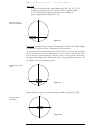
CAUTION! Do not turn alignment knobs B and C when the fine horizontal aiming screws E and the
coarse vertical aiming screws J and L are locked since this may damage the fine alignment mechanism.
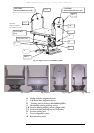
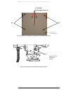
Front
(far side)
K
Caution! Do not touch these screws.
D
(
4 Screws)
C
B
E
J-R-3
L
M
(Red Ref.
Point)
J-L-2
Swing Base
J-L-3
J
-
R
-
2
Note: Knobs B and C are in the back of the TS5000.
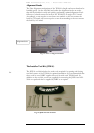
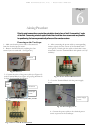
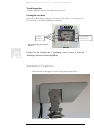
Fig 6.6: JMP-8 and AD-5000