


Chapter2–InstallingandCablingtheMultiVOIP
MultiVOIP®Voice/FaxoverIPGateways 13
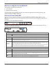
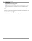
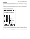
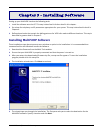
ForDIDchannelsonly
ForanychannelonwhichyouareusingtheDIDinterfacetype,youmustchangethejumperontheMultiVOIP
circuitcard.DIDisnotsupportedonthe–SSor–FXmodels.
1. Disconnectpower.UnplugtheACpowercordfromthewalloutletorfromthereceptacleontheMultiVOIP
unit.
2. Usinga#1Phillipsdriver,removethescrew(atbottomofunit,neartheback‐coverend)thatattachesthe
maincircuitcardtothechassisoftheMVP210.
3. Pullthemaincircuitcardoutabouthalfway.
4. IdentifythechannelsonwhichtheDIDinterfaceisused.
5. PositionthejumperforeachDIDchannelsothatitdoesnotconnectthetwojumperposts.ForDID
operationofaVOIPchannel,theMultiVOIPworksproperlyifyousimplyremovethejumperaltogether,but
thatisinadvisablebecausethejumpermightbeneededlaterifadifferenttelephonyinterface
isusedfor
thatVOIPchannel.
6. SlidethemaincircuitcardbackintotheMultiVOIPchassisandreplacethescrewatthebottomoftheunit.
J3
J7
J9J5
J11
FB3
LED2
R72
J1
S10
R 113
R114
LED12
J15
LED7
LED11 LED10
LED14
LED5 LED3 LED1
R58 R2R57
LED6 LED4LED9
R56
R74
R205
LED13
R55
LED8
Ch1
Ch2
Ch 2 Jumper
Block
MVP210 Circuit Board
JP1
JP8
as configured
for DID Interface
as shipped,
for non-DID interfaces
Ch 1 Jumper
Block
JP7
JP4
as configured
for DID Interface
P7