


ISI3334/4 Hardware/Driver Installation Manual
14
2.4 Hardware Installation Procedure
Perform the procedures in Table 2-1 to install the MultiModemISI
card(s) into your PC-ISA bus computer. Installation procedures
include setting the I/O address switch block and the IRQ jumper.
This section may be skipped if the defaults: I/O Address 210 Hex
and IRQ 10 are the values you have selected. However, if you are
installing multiple cards, step 4a of Table 2-1 describes how to
configure your card(s).
Table 2-1
MultiModemISI Installation Procedure
Step Procedure
1 Make sure your computer and any peripheral equipment
connected to it are turned off. Failure to do so may damage both
your ISI card(s) and your PC. The MultiModemISI may be
installed in a PC-AT, 386, 486, or Pentium equivalent ISA or
EISA bus computer.
2 Remove the cover of your computer as instructed in your
computer’s documentation.
3 Locate the unused slot(s) which you will be using for your
MultiModemISI card(s), and remove the slot cover(s) per the
instructions in your computer’s documentation.
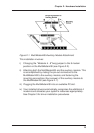
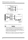
4 Check the settings of the I/O address switch and the IRQ jumper
to ensure that they are set properly for your installation.
Note: One MultiModemISI can be paired with an auxiliary
module (model #ISI3334/EC) when it interfaces with on-board
connectors attaching both cards; effectively providing 8 modem
functionality.