


Chapter 2 - Hardware Installation
15
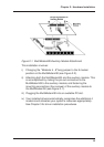
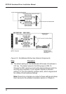
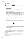
Figure 2-1. MultiModemISI/Auxiliary Module Attachment
This installation involves:
i) Changing the
"Modems 4 - 8"
berg jumper to the 8 modem
position on the MultiModemISI (see Figure 2-2).
ii) Attaching both the MultiModemISI and the auxiliary module. This
is accomplished by mating the pin-out connectors to the
MultiModemISI to the auxiliary module; and fastening the
mounting connections (four screws) of the auxiliary module to
the MultiModemISI (see Figure 2-1).
iii) Plugging the MultiModemISI into an available PC slot.
iv) Your installed drivers automatically recognizes the additional 4
modems and allocates your system's resources appropriately.
See Chapter 3 for driver installation procedures.