


Chapter 5 Signal Connections
NI 7340 User Manual 5-4 ni.com
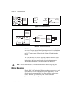
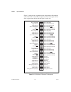
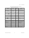
Motion Axis Signals
The following signals control the servo amplifier or stepper driver.
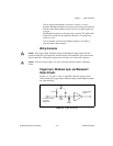
• Analog Output <1..4>—These 16-bit DAC outputs are typically
the servo command outputs for each axis. They can drive the
industry-standard ±10 V output, and can be software limited to
any positive or negative voltage range. They also feature
a software-programmable voltage offset.
Although typically used as the command output of an axis control
loop, unused DACs also can function as independent analog outputs
for general-purpose control.
• Analog Output Ground—To help keep digital noise separate from the
analog DAC outputs, there is a separate return connection. Use this
analog ground connection and not Digital Ground (digital I/O
reference) as the reference for the DAC outputs when connecting to
servo amplifiers.
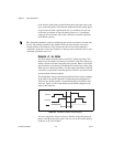
• Axis <1..4> Step (CW) and Dir (CCW)—These open-collector signals
are the stepper command outputs for each axis. The 7340 supports both
major industry standards for stepper command signals: step and
direction, or independent CW and CCW pulse outputs.
The output configuration and signal polarity is software programmable
for compatibility with various third-party drives, as follows:
– When step and direction mode is configured, each commanded
step (or microstep) produces a pulse on the step output. The
direction output signal level indicates the command direction of
motion, either forward or reverse.
– CW and CCW mode produces pulses (steps) on the CW output for
forward-commanded motion and pulses on the CCW output for
reverse-commanded motion.
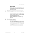
In either case, you can set the active polarity of both outputs to
active-low (inverting) or active-high (non-inverting). For example,
with step and direction, you can make a logic high correspond to either
forward or reverse direction.
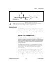
The Step (CW) and Dir (CCW) outputs are driven by high-speed
open-collector TTL buffers that feature 64 mA sink current capability
and built-in 3.3 kΩ pull-up resistors to +5 V.
Caution Do not connect these outputs to anything other than a +5 V circuit. The output
buffers will fail if subjected to voltages in excess of +5.5 V.