


Chapter 5 Signal Connections
NI 7340 User Manual 5-16 ni.com
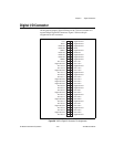
The 32-bit digital I/O port is configured in hardware as four 8-bit digital I/O
ports. The bits in a port are typically controlled and read with byte-wide
bitmapped commands.
All digital I/O lines have programmable direction and polarity. Each output
circuit can sink and source 24 mA.
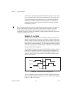
The DPull pin controls the state of the input pins at power-up. Connecting
DPull to +5 V or leaving it unconnected configures all pins in all ports for
100 kΩ pull-ups. Connecting DPull to ground configures the ports for
100 kΩ pull-downs.
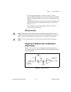
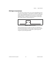
PWM Features
The 7340 provides two pulse width modulation (PWM) outputs on the
digital I/O connector. The PWM outputs generate periodic waveforms
whose period and duty cycles can be independently controlled through
software commands. The PWM is comparable to a digital representation of
an analog value because the duty cycle is directly proportional to the
expected output value. PWM outputs are typically used for transmitting an
analog value through an optocoupler. A simple lowpass filter turns a PWM
signal back into its corresponding analog value. You have the option to use
the PCLK input instead of the internal source as the clock for the PWM
generators.
Note These signals are configured in software and are in no way associated with the
PID servo control loop. Refer to the NI-Motion User Manual for more information.
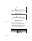
RTSI Connector
The physical RTSI bus interface varies depending on the type of 7340
controller.
The PXI-7340 uses the PXI chassis backplane to connect to other
RTSI-capable devices.
The PCI-7340 uses a ribbon cable to connect to other RTSI-capable PCI
devices.