


Chapter 5 Signal Connections
© National Instruments Corporation 5-7 NI 7340 User Manual
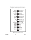
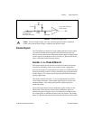
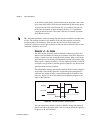
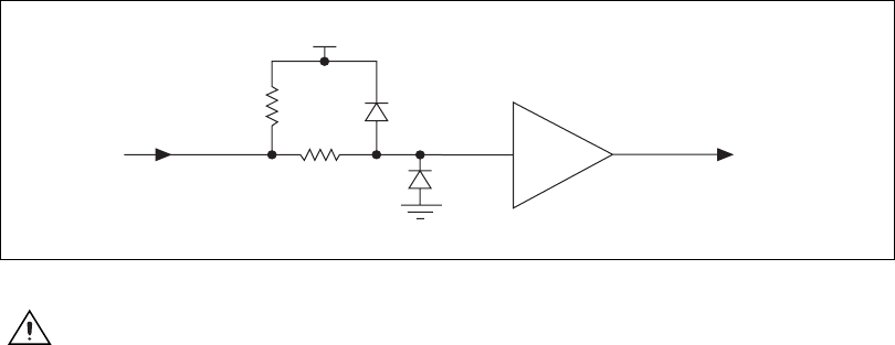
Figure 5-2. Limit and Home Input Circuit
Caution
Excessive input voltages can cause erroneous operation and/or component
failure. Verify that the input voltage is within the specification range.
Encoder Signals
The 7340 offers four channels of single-ended quadrature encoder inputs.
All National Instruments power drives and UMI accessories provide
built-in circuitry that converts differential encoder signals to single-ended
encoder signals. Each channel consists of a Phase A, Phase B, and Index
input, as described in the following sections.
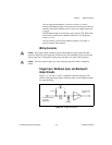
Encoder <1..4> Phase A/Phase B
The encoder inputs provide position and velocity feedback for absolute
and relative positioning of axes in any motion system configuration.
If an encoder resource is not needed for axis control, it is available for other
functions including position or velocity monitoring, digital potentiometer
encoder inputs, or as a master encoder input for master/slave (electronic
gearing) applications.
The encoder channels (Encoder <1..4>) are implemented in an FPGA
and are high performance with extended input frequency response and
advanced features, such as high-speed position capture inputs and
breakpoint outputs.
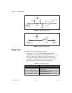
An encoder input channel converts quadrature signals on Phase A and
Phase B into 32-bit up/down counter values. Quadrature signals are
generated by optical, magnetic, laser, or electronic devices that provide
two signals, Phase A and Phase B, that are 90° out of phase. The leading
phase, A or B, determines the direction of motion. The four transition states
74FCT244
1 kΩ
1/8 W
From the external
connector limit
and home switch pins
To the limit and home
switch circuits
DGND
Vcc
3.3 kΩ