


Chapter 5 Signal Connections
© National Instruments Corporation 5-11 NI 7340 User Manual
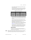
You can program breakpoints as absolute, modulo, or relative
positions. Breakpoint outputs can be preset to a known state so that the
transition when the breakpoint occurs can be low to high, high to low,
or toggle.
The breakpoint outputs are driven by open-collector TTL buffers that
feature 64 mA sink current capability and built-in 3.3 kΩ pull-up
resistors to +5 V.
You can directly set and reset breakpoint outputs to use them as
general-purpose digital outputs.
Wiring Concerns
Caution Keep trigger input, shutdown input, and breakpoint output signals and their
ground connections wired separately from the motor driver/amplifier signal and encoder
signal connections. Wiring these signals near each other can cause faulty operation.
Caution Excessive input voltages can cause erroneous operation and/or component
failure.
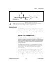
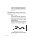
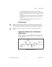
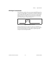
Trigger Input, Shutdown Input, and Breakpoint
Output Circuits
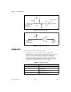
Figures 5-5, 5-6, and 5-7 show a simplified schematic diagram of the
circuits used by the trigger inputs, shutdown inputs, and breakpoint outputs
for signal buffering.
Figure 5-5. Trigger Input Circuit
74FCT244
1 kΩ
1/8 W
From the external
connector
trigger pins
To the trigger
circuits
DGND
Vcc
3.3 kΩ