


Chapter 5 Signal Connections
© National Instruments Corporation 5-9 NI 7340 User Manual
Wiring Concerns
The encoder inputs are connected to quadrature decoder/counter circuits.
It is very important to minimize noise at this interface. Excessive noise on
these encoder input signals may result in loss of counts or extra counts and
erroneous closed-loop motion operation. Verify the encoder connections
before powering up the system.
Caution Wire encoder signals and their ground connections separately from all other
connections. Wiring these signals near the motor drive/amplifier or other signals can cause
positioning errors and faulty operation.
Encoders with differential line driver outputs are strongly recommended
for all applications and must be used if the encoder cable length is longer
than 3.05 m (10 ft). Shielded, 24 AWG wire is the minimum recommended
size for the encoder cable. Cables with twisted pairs and an overall shield
are recommended for optimized noise immunity.
All National Instruments power drives and UMI accessories provide
built-in circuitry that converts differential encoder signals to single-ended
encoder signals.
Caution Unshielded cable can cause noise to corrupt the encoder signals, resulting in lost
counts and reduced motion system accuracy.
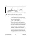
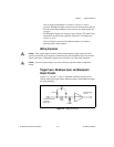
Encoder Input Circuit
Figure 5-4 shows a simplified schematic diagram of the circuit used for
the Phase A, Phase B, and Index encoder inputs. Both phases A and B are
required for proper encoder counter operation, and the signals must support
the 90° phase difference within system tolerance. The encoder and Index
signals are conditioned by a software-programmable digital filter inside
the FPGA. The Index signal is optional but highly recommended and
required for initialization functionality with the Find Index function.