


Chapter 5 Signal Connections
NI 7340 User Manual 5-8 ni.com
of the relative signal phases provide distinct pulse edges that cause count
up or count down pulses in the direction determined by the leading phase.
A typical encoder with a specification of N (N = number) lines per unit
of measure (revolutions or linear distance) produces 4 × N quadrature
counts per unit of measure. The count is the basic increment of position
in NI-Motion systems.
Tip Determine quadrature counts by multiplying the encoder resolution in encoder lines
by four. The encoder resolution is the number of encoder lines between consecutive
encoder marker or Z-bit indexes. If the encoder does not have an index output, the
resolution is referred to as lines per revolution, or lines per unit of measure, such as inch,
centimeter, millimeter, and so on.
Encoder <1..4> Index
The Index input is primarily used to establish a reference position. This
function uses the number of counts per revolution or the linear distance to
initiate a search move that locates the index position. When a valid Index
signal transition occurs during a Find Reference routine, the position of the
Index signal is captured accurately. Use this captured position to establish
a reference zero position for absolute position control or any other motion
system position reference required.
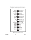
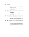
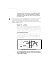
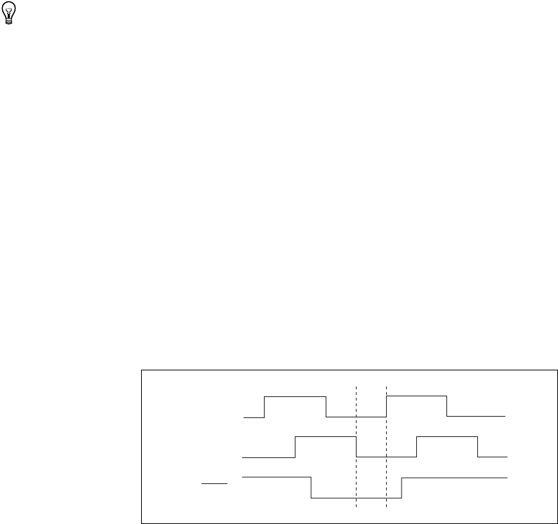
The default MAX settings guarantee that the Find Index routine completes
successfully if the encoder generates a high index pulse when phases A
and B are low and the encoder is connected through an NI UMI or drive
accessory. Figure 5-3 shows the default encoder phasing diagram at the
inputs to the controller.
Figure 5-3. Quadrature Encoder Phasing Diagram
You can set the index reference criteria in MAX to change the pattern of
phases A and B for the index search. You also can set the encoder polarity
for phases A, B, and I in MAX.
Phase A
Phase B
Index