


© National Instruments Corporation 3-1 6527 User Manual
3
Making Signal Connections
This chapter describes the pin arrangement, signal names, and signal
connections on your 6527 device.
Caution
Connections that exceed any of the maximum ratings of input or output signals
on your 6527 device can damage the board and your computer. Pay careful attention to
the maximum input ratings included with the description of each signal in this chapter.
National Instruments is not liable for any damages resulting from signal connections that
exceed these maximum ratings.
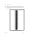
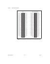
I/O Connector
The I/O connector for the 6527 device has 100 pins that you can connect to
50-pin accessories with the R1005050 cable or to 100-pin accessories with
the shielded SH100100-F cable. Figure 3-1 shows the pin assignments for
the 6527 I/O connector. A signal description follows the figure.