


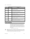

Chapter 3 Making Signal Connections
6527 User Manual 3-10 ni.com
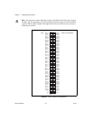
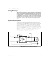
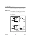
Solid-State Relay Outputs
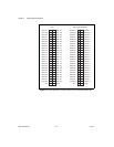
On a 6527 device, I/O connector pins 51 through 98, shown in Figure 3-1,
represent the terminals of the solid-state relays.
Output Channels
The output channels of a 6527 device are solid-state relays containing an
LED and two MOSFETs connected togetherto form a bidirectional switch.
The LH1546 is a solid-state relay. Depending on how the load is connected
to the terminals, an output can either source or sink currents.
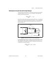
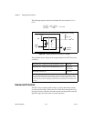
Figure 3-5 shows two signal connection examples for driving a load with
these solid-state relays.
Figure 3-5. Signal Connections for Solid-State Relays
Load
R
S
I
f
+5 V
Supply
+
–
Isolation
Isolated
Ground
Digital
Logic
390
DIG+
6527
DIG–
Load
R
S
I
f
+5 V
Supply
+
–
Isolation
Isolated
Ground
Digital
Logic
390
DIG+
6527
DIG–
a. Sinking Current
b. Sourcing Current
35
35
LH1546
LH1546