


Chapter 3 Making Signal Connections
6527 User Manual 3-12 ni.com
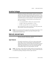
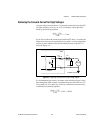
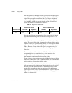
The following equation shows the minimum sink current when V
OUT
is
0.5 V:
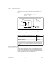
Figure 3-6. Signal Connections for Driving TTL Voltages
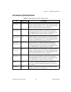
The maximum power ratings for the output channels on a 6527 device are
as follows:
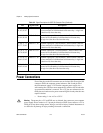
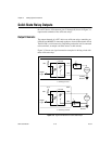
Overcurrent Protection
The 6527 device outputs include circuitry to protect them from currents
over the specified range. When excessive current flows through the relay,
the relay increases resistance. Once the current level drops back under the
specified range, the relays return to normal operation.
Maximum DC voltage across the terminals (V
OUT
) 60 VDC
Maximum AC voltage across the terminals (V
OUT
) 30 V
RMS
(42 V
Peak
)
Maximum current (I
f
) 120 mA
1
1
With allrelays carrying120 mA and all inputs drivento 28 V,the total power dissipation
can approach 20 W. The maximum switching capacity in PCI and CompactPCI systems
mustbe deratedaccording totheambient temperatureand coolingcapacityof yoursystem
to preventthe device fromoverheating. (The PXIchassis has built-in fans to handle 25 W
per slot.)
0.5V
35
Ω
------------
5V 0.5V–()
5k
Ω
-----------------------------– 13.4 mA=
+5 V
R
L
=5k
V
OUT
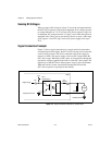
Isolation
Isolated
Ground
Digital
Logic
390
To External +5 V Supply
I
f
35
6527