


Chapter 3 Making Signal Connections
6527 User Manual 3-8 ni.com
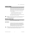
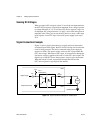
Sensing DC Voltages
When you apply a DC voltage of at least2 V across the two input terminals,
the 6527 device registers a logic high for that input. If no voltage is present
(a voltage difference of 1 V or less), the 6527 device registers a logic low
for that input. DC voltages between 1 V and 2 V are invalid and register an
unreliable value. Thus, you can use the 6527 device to sense a wide range
of DC signals—from TTL logic levels to DC power supply levels up to
28 V.
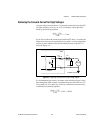
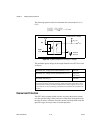
Signal Connection Example
Figure 3-3 shows signal connections for a supply and load connected to
an isolated input. In this figure, the 6527 device is being used to sense that
a load is being powered. The load is connected to the power supply by
means of a switch. This power supply can be any DC voltage within the
6527 device range. When the switch is open, no current flows through the
load and no voltage is applied to the load or to the 6527 device input. The
digital logic of the 6527 device then registers a logic low for the channel.
When the switch is closed, current flows through the LED and the
6527 device registers a logic high for the channel.
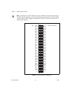
Figure 3-3. Signal Connection Example for Isolated Input
0.25 W
6527
5211
Optoisolator
Isolation
15 k
3k
Load
Digital Logic
Computer Ground
+5 V
DIG+
DIG–
Isolated Ground
Supply
+
–