


Chapter 4 Using the 6527
6527 User Manual 4-6 ni.com
• Bit 1 is connected to a limit sensor; the 6527 detects rising edges on
the sensor, which correspond to over-limit conditions.
• Bit 0 is connected to a switch. Your software can react to any switch
closure, represented by a falling edge. If the switch closure is noisy,
you should also enable digital filtering for at least this line.
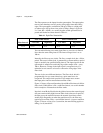
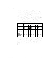
In this example, the 6527 reports rising edges only on bit 1, falling edges
only on bit 0, and rising and falling edges on bits 7, 6, 5, and 4. The 6527
reports no changes for bits 3 and 2. After receiving notification of a change,
you can read the port to determine the current values of all eight lines.
If you anticipate noisy or rapidly changing input lines, use digital filtering
with change notification to reduce the changes to a manageable number;
excessive notifications can hurt system performance. For example, if you
want to limit the rate of notifications and interrupts to a maximum of one
change per line every 10 ms, set a filter interval of 10 ms. This causes
glitches and all other transitions that occur for less than 10 ms to be
ignored.
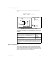
Table 4-2. Change Notification Example
Bit
7 6 5 4 3 2 1 0
Changes to
detect
— —
Enable
rising- edge
detection
yes yes yes yes no no yes no
Enable
falling- edge
detection
yes yes yes yes no no no yes