


Chapter 4 Using the 6527
6527 User Manual 4-4 ni.com
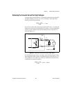
The filter operates on the inputs from the optocouplers. The optocouplers
turn on faster than they turn off, passing rising edges faster than falling
edges. The optocouplers can therefore add up to 100 µs to a high pulse
or subtract up to 100 µs from a low pulse (a 100 µs change is typical at
I
f
=5mA, RL=100Ω). As a result, the pulse widths guaranteed to be
passed and blocked are those shown in Table 4-1.
You can enable filtering on as many input lines as you wish. All filtered
lines share the same timing interval. The interval ranges from 1 ms to
100 ms.
Internally, the filter uses two clocks. The first, a sample clock, has a 100 ns
period. The second, a filter clock, is generated by a counter and has a period
equal to one half your specified timing interval. The input signal from the
optocoupler is sampled on each rising edge of the sample clock—every
100 ns. However, a change in the input signal is recognized only if it
maintains its new state for at least two consecutive rising edges of the
filter clock.
The two clocks serve different functions. The filter clock, which is
programmable, lets you control how long a pulse must last to be
recognized. The sample clock provides a fast sample rate to ensure
that input pulses remain constant between filter clocks.
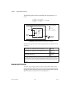
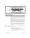
Figure 4-2 shows a filter configuration with an 800 ns filter interval (400 ns
filter clock). While 800 ns is not a valid filter interval, we use this number
in this example to illustrate how the filter works.
In periods A and B, the filter blocks the glitches because the external signal
does not remain steadily high from one filter clock to the next. In period C,
the filter passes the transition because the external signal does remain
steadily high. Depending on when the transition occurs, the filter may
require up to two filter clocks—one full filter interval—to pass a transition.
Figure 4-2 shows a rising (0-to-1) transition; the same filtering applies to
falling (1-to-0) transitions.
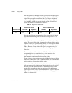
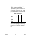
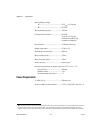
Table 4-1. Digital Filter Characteristics
Filter Interval
Pulse Width Passed Pulse Width Blocked
Low Pulse High Pulse Low Pulse High Pulse
t
interval
t
interval
+ 100 µs t
interval
– 100 µs (t
interval
/2) + 100 µs
(t
interval
/2) – 100 µs