


Chapter 3 Making Signal Connections
6527 User Manual 3-2 ni.com
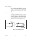
Note
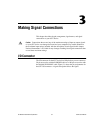
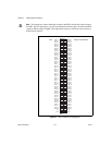
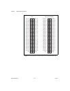
For input ports, connect the higher voltage to the DIG+ pin and the lower voltage to
the DIG– pin. For output ports, you can connect signals to the two pins of each line without
regard to which voltage is higher. The output lines consist of solid-state relays and act as
bidirectional switches.
Figure 3-1. 6527 Connector Pin Assignments
50 100
49 99
48 98
47 97
46 96
45 95
44 94
43 93
42 92
41 91
40 90
39 89
38 88
37 87
36 86
35 85
34 84
33 83
32 82
31 81
30 80
29 79
28 78
27 77
26 76
25 75
24 74
23 73
22 72
21 71
20 70
19 69
18 68
17 67
16 66
15 65
14 64
13 63
12 62
11 61
10 60
959
858
757
656
555
454
353
252
151
GND GND
+5V +5V
DIG–0.0 DIG–3.0
DIG+0.0 DIG+3.0
DIG–0.1 DIG–3.1
DIG+0.1 DIG+3.1
DIG–0.2 DIG–3.2
DIG+0.2 DIG+3.2
DIG–0.3 DIG–3.3
DIG+0.3 DIG+3.3
DIG–0.4 DIG–3.4
DIG+0.4 DIG+3.4
DIG–0.5 DIG–3.5
DIG+0.5 DIG+3.5
DIG–0.6 DIG–3.6
DIG+0.6 DIG+3.6
DIG–0.7 DIG–3.7
DIG+0.7 DIG+3.7
DIG–1.0 DIG–4.0
DIG+1.0 DIG+4.0
DIG–1.1 DIG–4.1
DIG+1.1 DIG+4.1
DIG–1.2 DIG–4.2
DIG+1.2 DIG+4.2
DIG–1.3 DIG–4.3
DIG+1.3 DIG+4.3
DIG–1.4 DIG–4.4
DIG+1.4 DIG+4.4
DIG–1.5 DIG–4.5
DIG+1.5 DIG+4.5
DIG–1.6 DIG–4.6
DIG+1.6 DIG+4.6
DIG–1.7 DIG–4.7
DIG+1.7 DIG+4.7
DIG–2.0 DIG–5.0
DIG+2.0 DIG+5.0
DIG–2.1 DIG–5.1
DIG+2.1 DIG+5.1
DIG–2.2 DIG–5.2
DIG+2.2 DIG+5.2
DIG–2.3 DIG–5.3
DIG+2.3 DIG+5.3
DIG–2.4 DIG–5.4
DIG+2.4 DIG+5.4
DIG–2.5 DIG–5.5
DIG+2.5 DIG+5.5
DIG–2.6 DIG–5.6
DIG+2.6 DIG+5.6
DIG–2.7 DIG–5.7
DIG+2.7 DIG+5.7
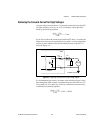
Input Output with Readback