Index
© National Instruments Corporation I-3 6527 User Manual
power connections, 3-6
power rating, 3-6
power requirement specifications, A-2
power-on and power-off conditions, 3-13
PXI, using with CompactPCI, 1-2
R
R1005050 cableassembly. Seecable assembly
connectors.
reducing forward current for high
voltages, 3-9
relay outputs. See solid-state relay outputs.
requirements for getting started, 1-2
S
safety information, 1-5
safety specifications, A-3
self-resetting fuse, 3-6
sensing DC voltages, 3-8
signal connections, 3-1 to 3-13
exceeding maximum ratings
(warning), 3-1
I/O connector, 3-1 to 3-6
cable assembly connectors, 3-3 to 3-4
pin assignments (figure), 3-2
port functionality (table), 3-3
signal descriptions (table), 3-5 to 3-6
isolation voltages, 3-7
optically isolated inputs, 3-7 to 3-9
input channels, 3-7
reducing forward current for high
voltages, 3-9
sensing DC voltages, 3-8
signal connection example, 3-8
power connections, 3-6
solid-state relay outputs, 3-10 to 3-13
output channels, 3-10 to 3-12
overcurrent protection, 3-12 to 3-13
power-on and power-off
conditions, 3-13
software installation, 2-1
software programming choices, 1-3 to 1-4
National Instruments application
software, 1-3
NI-DAQ driver software, 1-3 to 1-4
solid-state relay outputs, 3-10 to 3-13
output channels, 3-10 to 3-12
driving a load
(example), 3-10 to 3-11
maximum power ratings, 3-12
sinking and sourcing current
(example), 3-11 to 3-12
overcurrent protection, 3-12 to 3-13
power-on and power-off conditions, 3-13
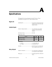
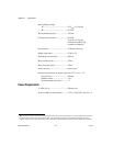
specifications, A-1 to A-2
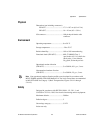
specifications, A-1 to A-3
digital I/O, A-1
environment, A-3
isolated inputs, A-1
physical, A-3
power requirements, A-2
relay outputs, A-1 to A-2
safety, A-3
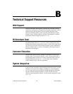
system integration, by National
Instruments, B-1
T
technical support resources, B-1 to B-2
U
unpacking 6527 devices, 1-6
W
Web support from National Instruments, B-1
Worldwide technical support, B-2


