


Chapter 3 Making Signal Connections
© National Instruments Corporation 3-5 6527 User Manual
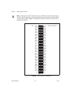
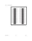
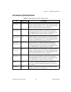
I/O Connector Signal Descriptions
Table 3-2.
Signal Descriptions for 6527 I/O Connector Pins
Pin Signal Name Description
33, 35,37, 39,
41, 43, 45, 47
DIG+0.<7..0> Isolated input port 0, positive terminals—Take measurements
at these terminals. These terminals should be positive relative
to their corresponding DIG– lines. A logic high (data bit of 1)
indicates input voltage and current are present.
34, 36,38, 40,
42, 44, 46, 48
DIG–0.<7..0> Isolated input port 0, negative terminals—Each of these
terminals serves as the reference terminal from which the
corresponding DIG+ line is measured. A logic high (data bit
of 1) indicates input voltage and current are present.
17, 19,21, 23,
25, 27, 29, 31
DIG+1.<7..0> Isolated input port 1, positive terminals—Take measurements
at these terminals. These terminals should be positive relative
to their corresponding DIG– lines. A logic high (data bit of 1)
indicates input voltage and current are present.
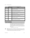
18, 20,22, 24,
26, 28, 30, 32
DIG–1.<7..0> Isolated input port 1, negative terminals—Each of these
terminals serves as the reference terminal from which the
corresponding DIG+ line is measured. A logic high (data bit
of 1) indicates input voltage and current are present.
1, 3, 5, 7, 9,
11, 13, 15
DIG+2.<7..0> Isolated input port 2, positive terminals—Take measurements
at these terminals. These terminals should be positive relative
to their corresponding DIG– lines. A logic high (data bit of 1)
indicates input voltage and current are present.
2, 4, 6, 8, 10,
12, 14, 16
DIG–2.<7..0> Isolated input port 2, negative terminals—Each of these
terminals serves as the reference terminal from which the
corresponding DIG+ line is measured. A logic high (data bit
of 1) indicates input voltage and current are present.
49, 99 +5 V +5 Volts—Thesepinsarefusedforupto1Atotalof+4.5
to +5.25 V from the computer power supply. These pins are
not isolated.
50, 100 GND Ground—These pins are connected to the computer ground
reference. These pins are not isolated.