


© National Instruments Corporation 2-1 NI 783xR User Manual
2
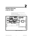
Hardware Overview
of the NI 783x R
This chapter presents an overview of the hardware functions and
I/O connectors on the NI 783xR.
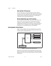
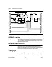
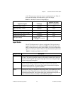
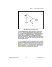
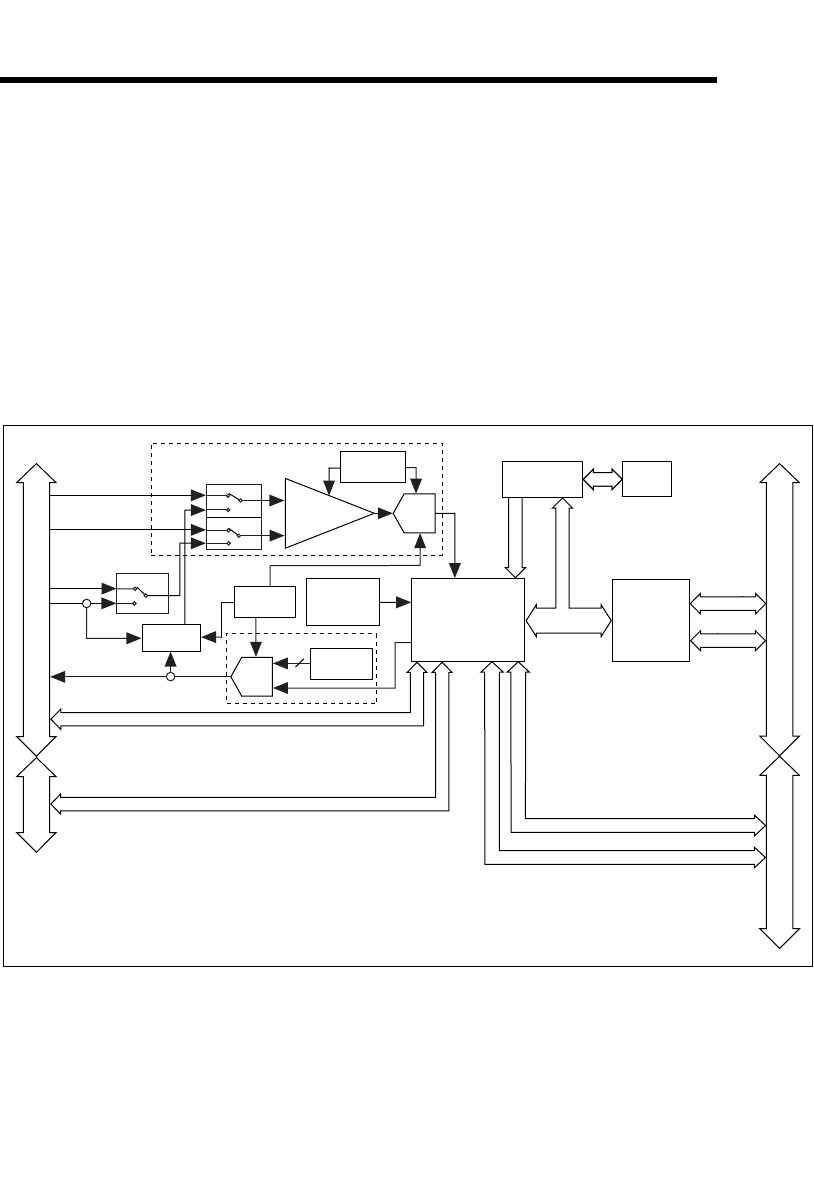
Figure 2-1 shows a block diagram for the NI 7830R. Figure 2-2 shows a
block diagram for the NI 7831R/7833R.
Figure 2-1. NI 7830R Block Diagram
+
AI+
AI–
PCI/PXI/CompactPCI Bus
Input Mux
Instrumentation
Amplifier
Input Mode Mux
AISENSE
AIGND
16-Bit
DAC
x4 Channels
2
x4 Channels
Configuration
Flash
Memory
User-
Configurable
FPGA on RIO
Devices
Bus
Interface
Connector 1 (DIO)
Data/Address/
Control
Digital I/O (16)
Digital I/O (40)
Calibration
DACs
Configuration
Control
Connector 0 (MIO)
Calibration
DACs
Voltage
Reference
–
16-Bit
ADC
Temperature
Sensor
Calibration
Mux
RTSI/PXI Triggers
RTSI Bus
Address/Data
Control
PXI Local Bus (NI PXI-783
x
R only)