Chapter 2 Hardware Overview of the NI 783xR
© National Instruments Corporation 2-3 NI 783xR User Manual
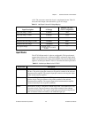
±10 V. The converters return data in two’s complement format. Table 2-1
shows the ideal output code returned for a given AI voltage.
Input Modes
The NI 783xR input mode is software configurable. The input channels
support three input modes—differential (DIFF), referenced single ended
(RSE), and nonreferenced single ended (NRSE). The selected input mode
applies to all the input channels. Table 2-2 describes the three input modes.
Table 2-1. Ideal Output Code and AI Voltage Mapping
Input Description AI Voltage
Output Code (Hex)
(Two’s Complement)
Full-scale range –1 LSB 9.999695 7FFF
Full-scale range –2 LSB 9.999390 7FFE
Midscale 0.000000 0000
Negative full-scale range +1 LSB –9.999695 8001
Negative full-scale range –10.000000 8000
Any input voltage —
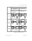
Table 2-2. Available Input Modes for the NI 783xR
Input Mode Description
DIFF When the NI 783xR is configured in DIFF input mode, each channel uses two
AI lines. The positive input pin connects to the positive terminal of the onboard
instrumentation amplifier. The negative input pin connects to the negative input
of the instrumentation amplifier.
RSE When the NI 783xR is configured in RSE input mode, each channel uses only its
positive AI pin. This pin connects to the positive terminal of the onboard
instrumentation amplifier. The negative input of the instrumentation amplifier
connects internally to the AI ground (AIGND).
NRSE When the NI 783xR is configured in NRSE input mode, each channel uses only
its positive AI pin. This pin connects to the positive terminal of the onboard
instrumentation amplifier. The negative input of the instrumentation amplifier on
each AI channel connects internally to the AISENSE input pin.
Output Code
32,768
----------------------------------
10.0 V×


