


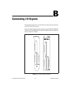
Appendix B Connecting I/O Signals
© National Instruments Corporation B-7 NI 783xR User Manual
DIO connector. These lines correspond to Slots <0..15> on an SSR
backplane in sequential order. You can connect to an SSR backplane
containing a number of channels unequal to the number of lines on the
NSC68-5050 cable header. In this case, you have access only to the
channels that exist on both the SSR backplane and the NSC68-5050 cable
header you are using.
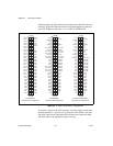
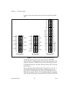
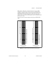
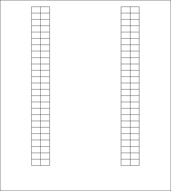
Figure B-4 shows the connector pinouts when using the NSC68-5050
cable.
Figure B-4. Connector Pinouts when Using the NSC68-5050 Cable
2
4
6
8
10
12
14
16
18
20
22
24
26
28
30
32
34
36
38
40
42
44
46
48
50
1
3
5
7
9
11
13
15
17
19
21
23
25
27
29
31
33
35
37
39
41
43
45
47
49
DIO23
DIO22
DIO21
DIO20
DIO19
DIO18
DIO17
DIO16
DIO15
DIO14
DIO13
DIO12
DIO11
DIO10
DIO9
DIO8
DIO7
DIO6
DIO5
DIO4
DIO3
DIO2
DIO1
DIO0
+5V
NC
NC
NC
NC
NC
NC
NC
NC
NC
DGND
DGND
DGND
DGND
DGND
DGND
DGND
DGND
DGND
DGND
DGND
DGND
DGND
DGND
DGND
DGND
2
4
6
8
10
12
14
16
18
20
22
24
26
28
30
32
34
36
38
40
42
44
46
48
50
1
3
5
7
9
11
13
15
17
19
21
23
25
27
29
31
33
35
37
39
41
43
45
47
49
NC
NC
NC
NC
NC
NC
NC
NC
DIO39
DIO38
DIO37
DIO36
DIO35
DIO34
DIO33
DIO32
DIO31
DIO30
DIO29
DIO28
DIO27
DIO26
DIO25
DIO24
+5V
NC
NC
NC
NC
NC
NC
NC
NC
NC
NC
NC
NC
NC
NC
NC
DGND
DGND
DGND
DGND
DGND
DGND
DGND
DGND
DGND
DGND
DIO 0–23 Connector
Pin Assignment
DIO 24–39 Connector
Pin Assignment