Appendix B Connecting I/O Signals
NI 783xR User Manual B-6 ni.com
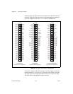
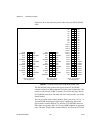
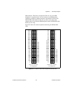
Figure B-3 shows the connector pinouts when using the NSC68-262650
cable.
Figure B-3. Connector Pinouts when Using NSC68-262650 Cable
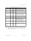
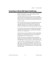
The NSC68-5050 cable connects the signals on the NI 783xR DIO
connectors directly to SSR backplanes for digital signal conditioning. This
cable has a 68-pin male VHDCI connector on one end that plugs into the
NI 783xR DIO connectors. The other end of this cable provides two 50-pin
female headers.
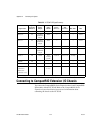
You can plug each of these 50-pin headers directly into an 8-, 16-, 24-, or
32-channel SSR backplane for digital signal conditioning. One of the
50-pin headers contains DIO<0..23> from the NI 783xR DIO connector.
These lines correspond to Slots <0..23> on an SSR backplane in sequential
order. The other 50-pin header contains DIO<24..39> from the NI 783xR
2
4
6
8
10
12
14
16
18
20
22
24
26
1
3
5
7
9
11
13
15
17
19
21
23
25
AO0
AOGND0
AO1
AO2
AOGND2
AO3
AO4
AOGND4
AO5
AO6
AOGND6
AO7
NC
NC
NC
AOGND1
NC
NC
AOGND3
NC
NC
AOGND5
NC
NC
AOGND7
NC
AO 0–7 Connector
Pin Assignment
2
4
6
8
10
12
14
16
18
20
22
24
26
1
3
5
7
9
11
13
15
17
19
21
23
25
AI0+
AIGND0
AI1+
AI2+
AIGND2
AI3+
AI4+
AIGND4
AI5+
AI6+
AIGND6
AI7+
AISENSE
AI0–
AI1–
AIGND1
AI2–
AI3–
AIGND3
AI4–
AI5–
AIGND5
AI6–
AI7–
AIGND7
NC
AI 0–7 Connector
Pin Assignment
2
4
6
8
10
12
14
16
18
20
22
24
26
28
30
32
34
36
38
40
42
44
46
48
50
1
3
5
7
9
11
13
15
17
19
21
23
25
27
29
31
33
35
37
39
41
43
45
47
49
NC
NC
NC
NC
NC
NC
NC
NC
DIO15
DIO14
DIO13
DIO12
DIO11
DIO10
DIO9
DIO8
DIO7
DIO6
DIO5
DIO4
DIO3
DIO2
DIO1
DIO0
+5V
NC
NC
NC
NC
NC
NC
NC
NC
NC
NC
NC
NC
NC
NC
NC
NC
NC
DGND
DGND
DGND
DGND
DGND
DGND
DGND
DGND
DIO 0–15 Connector
Pin Assignment


