


Chapter 3 Signal Connections
PCI-1200 User Manual 3-2 © National Instruments Corporation
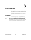
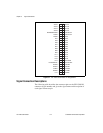
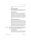
Figure 3-1.
PCI-1200 I/O Connector Pin Assignments
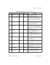
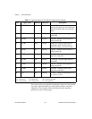
Signal Connection Descriptions
The following table describes the connector pins on the PCI-1200 I/O
connector by pin number and gives the signal name and description of
each signal connector pin.
+5 V
GATB2
CLKB1
OUTB1
OUTB0
EXTUPDATE*
PC7
PC5
PC3
PC1
PB7
PB5
PB3
PB1
PA7
PA5
PA3
PA1
DGND
AGND
AISENSE/AIGND
ACH6
ACH4
ACH2
ACH0
DGND
OUTB2
GATB1
EXTCONV*
EXTTRIG
PC6
PC4
CLKB2
GATB0
PC2
PC0
PB6
PB4
PB2
PB0
PA6
PA4
PA2
PA0
DAC1OUT
DAC0OUT
ACH7
ACH5
ACH3
ACH1
49 50
47 48
45 46
43 44
41 42
39 40
37 38
35 36
33 34
31 32
29 30
27 28
25 26
23 24
21 22
19 20
17 18
15 16
13 14
11 12
910
78
56
34
12