


Chapter 3 Signal Connections
© National Instruments Corporation 3-13 PCI-1200 User Manual
Single-Ended Connections for Floating Signal Sources
(RSE Configuration)
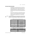
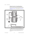
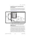
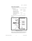
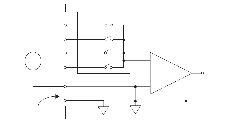
Figure 3-5 shows how to connect a floating signal source to a PCI-1200
board configured for RSE mode. Configure the PCI-1200 analog input
circuitry for RSE input to make these types of connections. Configuration
instructions are in the Analog I/O Configuration section of Chapter 2,
Installation and Configuration.
Figure 3-5.
Single-Ended Input Connections for Floating Signal Sources
Single-Ended Connections for Grounded Signal Sources
(NRSE Configuration)
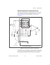
If you measure a grounded signal source with a single-ended configuration,
configure the PCI-1200 in the NRSE input configuration. The signal is
connected to the positive input of the PCI-1200 instrumentation amplifier
and the signal local ground reference is connected to the negative input of
the PCI-1200 instrumentation amplifier. Therefore, connect the ground
point of the signal to the AISENSE pin. Any potential difference between
the PCI-1200 ground and the signal ground appears as a common-mode
signal at both the positive and negative inputs of the instrumentation
amplifier and is therefore rejected by the amplifier. On the other hand, if
the input circuitry of the PCI-1200 is referenced to ground, such as in the
V
s
+
+
+
V
m
Measured
Voltage
Floating
Signal
Source
ACH0
AISENSE/AIGND
AGND
I/O Connector
1
2
3
8
9
PCI-1200 in RSE Configuration
11
ACH1
ACH2
ACH7
•
•
•
•
•
•
–
–
–