Chapter 3 Signal Connections
PCI-1200 User Manual 3-22 © National Instruments Corporation
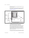
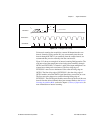
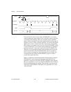
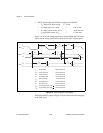
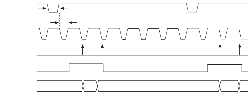
Figure 3-12.
Interval-Scanning Signal Timing
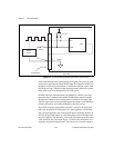
You use the final external control signal, EXTUPDATE*, to externally
control updating the output voltage of the 12-bit DACs and/or to generate
an externally timed interrupt. There are two update modes, immediate
update and delayed update. In immediate update mode the analog output is
updated as soon as a value is written to the DAC. If you select the delayed
update mode, a value is written to the DAC; however, the corresponding
DAC voltage is not updated until a low level on the EXTUPDATE* signal
is sensed. Furthermore, if you enable interrupt generation, an interrupt is
generated whenever a rising edge is detected on the EXTUPDATE* bit.
Therefore, you can perform externally timed, interrupt-driven waveform
generation on the PCI-1200. The EXTUPDATE* line is susceptible to
noise caused by switching lines and could generate false interrupts. We
recommend that the width of the EXTUPDATE* pulse be as short as
possible, but greater than 50 ns.
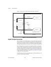
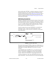
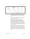
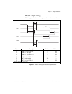
Figure 3-13 illustrates a waveform generation timing sequence using the
EXTUPDATE* signal and the delayed update mode. The DACs are
updated by a high level on the DAC OUTPUT UPDATE signal, which in
this case is triggered by a low level on the EXTUPDATE* line. CNTINT is
the signal that interrupts the computer. This interrupt is generated on the
rising edge of EXTUPDATE*. DACWRT is the signal that writes a new
value to the DAC.
OUTB1
EXTCONV*
CONVERT
GATE
t
w
= 50 ns
t
d
= 50 ns
ADC CH
CH1 CH0
CH1
CH0


