


1-12 System Overview
CPU Module Board
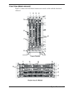
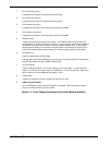
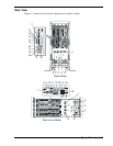
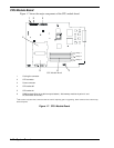
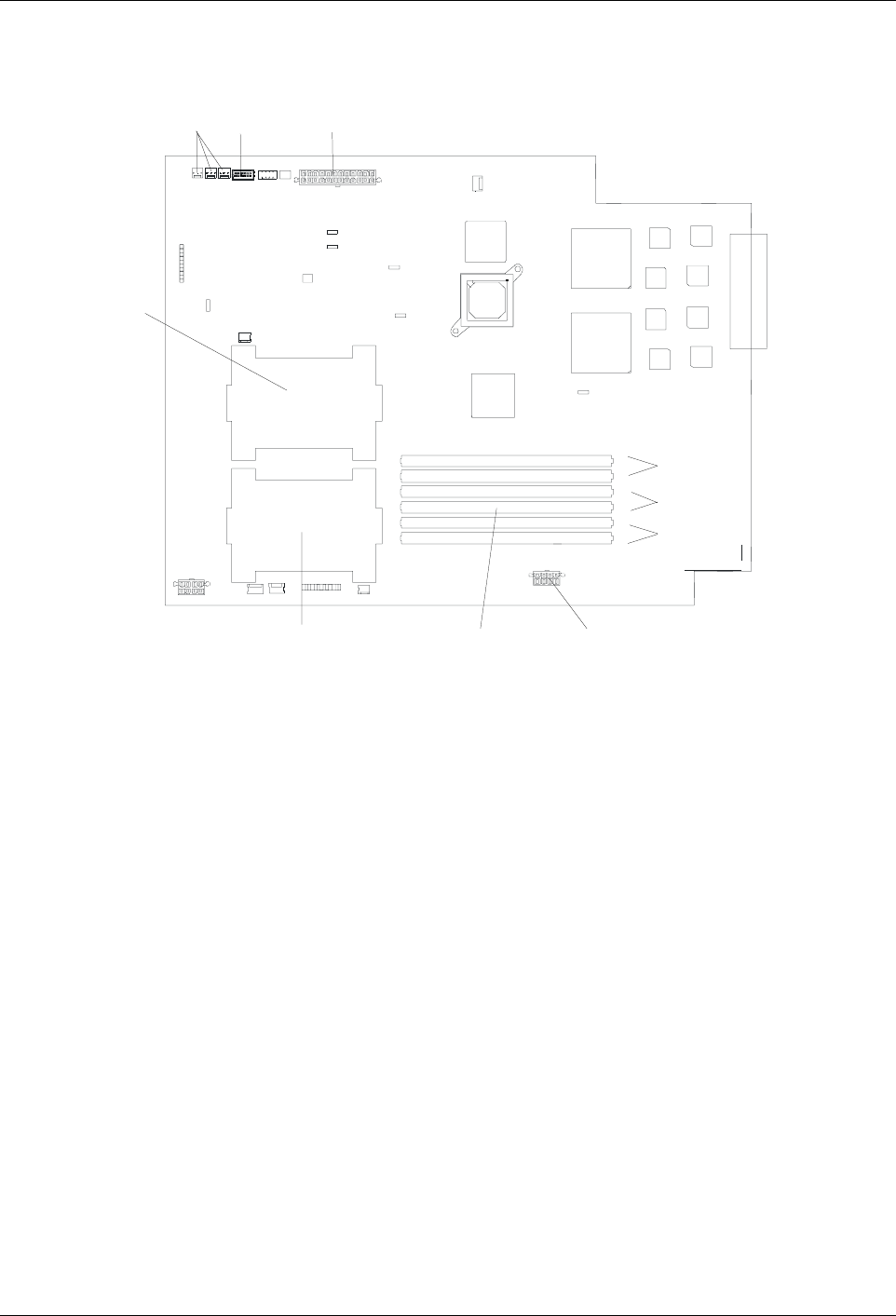
Figure 1-7 shows the major components of the CPU module board.
12
3
3
4
56
1
2
3
4
5
6
Group 1
Group 2
Group 3
CPU Module Board
1 Cooling fan connector
2 LED connector
3 Power connector
4CPU socket #2
5CPU socket #1
6 DIMM sockets (Slots #1 to #6 from top to bottom). Add memory modules in pairs: #1 and
#2, #3 and #4, #5 and #6.)
*This section only describes connectors that are used for replacing parts or upgrading. Other connectors have been setup
before shipment.
Figure 1-7. CPU Module Board