


Upgrading Your System 4-15
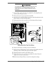
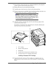
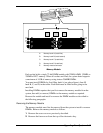
J16
J15
J12
J11
J8
J7
J3
J4
J14
J13
J10
J9
J6
J5
J1
J2
D
C
B
A
E
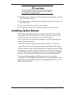
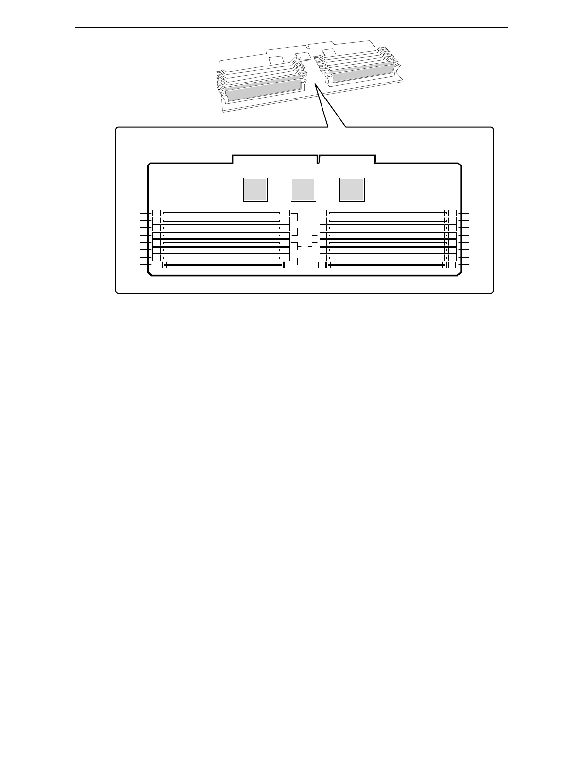
A. Memory bank A (install first)
B. Memory bank B (install second)
C. Memory bank C (install third)
D. Memory bank D (install last)
E. Memory module connector
Memory Module
Each socket holds a single 72-bit DIMM module with 32MB, 64MB, 128MB, or
256MB of ECC memory. When all sockets are filled, the system board supports
a maximum of 4 GB of memory using sixteen 256MB DIMMs.
You must install DIMMs by first filling bank A (see above figure), then fill
bank B, C, and D, in that order. Each bank must be filled before going to the
next bank.
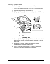
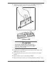
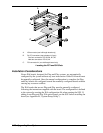
Installing DIMMs requires that you first remove the memory module from the
system, then add (or remove) DIMMs to the memory module as required.
Remove the module and install or remove the DIMM modules as described in
the following paragraphs.
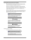
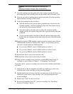
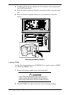
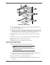
Removing the Memory Module
The memory module must first be removed from the system to install or remove
DIMMs. Remove the memory module as follows.
1. Remove the access cover as previously described.
2. Remove the foam cover from the top of the electronics bay.