


700 Series Managed Switch User’s Guide for Software v2.1
Cabling Guidelines B-7
SM-10004-02
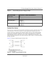
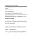
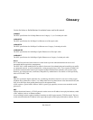
Figure B-4 shows the RJ-45 plug and RJ-45 connector.
Figure B-4: RJ-45 Plug and RJ-45 Connector with Built-in LEDs
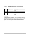
Table B-2 lists the pin assignments for the 10/100 Mbps RJ-45 plug and the RJ-45 connector.
Table-B-2. 10/100 Mbps RJ-45 Plug and RJ-45 Connector Pin Assignments
Table E-2 lists the pin assignments for the 100/1000 Mbps RJ-45 plug and the RJ-45 connector.
PIN NORMAL ASSIGNMENT ON
PORTS 1 TO 8
UPLINK ASSIGNMENT ON
PORT 8
1 Input Receive Data + Output Transmit Data +
2 Input Receive Data – Output Transmit Data –
3 Output Transmit Data + Input Receive Data +
6 Output Transmit Data – Input Receive Data –
4, 5, 7, 8 Internal termination, not used for data transmission