


2
INSTRUCTIONS FOR USE:
Materials and Equipment
Revolution Catheter
Sterile PIM cover
10 in. extension tubing
3 cc and 10 cc syringes
3-way stop cock
Pre-formed guide catheter [0.064 in. (1.63 mm) I.D. min.] with Y-adapter
assembly*
In-Vision Gold imaging system with software V5.0 or higher, Volcano s5 and
Volcano s5i imaging system*
Heparinized, physiologic saline solution*
Guide wire, 0.014 in. (0.36 mm) max. diameter*
*not packaged with catheter
Inspection Prior to Use
Carefully inspect the package prior to use for any breach of the sterile barrier
or damage to the contents. If the sterile barrier integrity is compromised or the
contents damaged, contact your Volcano Corporation representative.
Preparation For Use
Refer to the operator’s manual or user’s guide for instrumentation and PIM
Setup.
Using sterile technique, remove the catheter from its sterile packaging.
Remove the Packaging Coil protecting the catheter. Retract the movable
Imaging Core completely to the proximal position via the telescope shaft.
Connect the 3 cc and 10 cc syringes to the 3-way stopcock, then connect the
assembly to the extension tube and fill both syringes with heparinized saline.
Ensure that all air is expelled from the system. Do not use if saline leaks from
any location other than the vent port in the monorail section.
Connect the extension tube to the one-way valve on the catheter hub. The 10
cc syringe is to be used as a reservoir for refilling the 3 cc flushing syringe.
Flush the imaging catheter TWICE continuously with 3 cc volume each time.
DO NOT USE EXCESSIVE PRESSURE. Advance the imaging core to its fully
distal position; via the telescope shaft.
Connect the imaging catheter to the PIM by inserting the proximal end of the
connector through the opening in the Sterile PIM cover, gently twisting the
connector until it locks into place. To ensure that the hub is fully seated in the
PIM, gently tug on the catheter hub.
Begin imaging by pressing the IMAGE button on the PIM long enough to
ensure proper function of the catheter by observing a pattern of partial bright
concentric rings on the monitor. Refill the 10 cc syringe as needed and
reattach to the stopcock without introducing air into the line.
Place Guide Catheter
Prepare the entry site with a sheath introducer according to the standard practice.
Prior to inserting the imaging catheter, ensure the patient has been prepared
using standard procedure for interventional treatment.
Backload the guide wire into the distal end of the catheter. Advance the
guidewire into the catheter until the guidewire exits from the wire exit port. Place
the guide catheter and Y-adapter. Introduce the guidewire and advance it to the
region of interest. Introduce imaging catheter into guide catheter.
Note: Guidewires that supply more stiffness near the distal tips are recommended.
Note: Always wipe down the guidewire with heparinized saline prior to loading
the catheter onto the guidewire.
CAUTION: Never advance the imaging catheter without guidewire support.
CAUTION: Never advance or withdraw the imaging catheter without the
imaging core assembly in the most distal position.
CAUTION: Never advance or withdraw the imaging catheter without direct,
fluoroscopic visualization.
CAUTION: Never advance the distal tip of the imaging catheter near the very
floppy end of the guidewire. This part of the guidewire will not adequately
support the catheter. A catheter advanced to this portion may not follow the
guidewire when it is retracted and cause the guide wire to buckle into a loop.
The catheter may then drag along the inside of vessel and catch on the guide
catheter tip. If this occurs, remove the catheter assembly, guidewire and the
guide catheter together. If the catheter is advanced too near the end of the
guidewire, advance the guidewire while holding the imaging catheter steady. If
this fails, withdraw the catheter and guidewire together.
Continue to advance the imaging catheter into the guide catheter, up to the
femoral marker. Tighten the hemostasis valve on the guide catheter’s Y-
adapter. Tighten only enough to prevent fluid/blood leakage.
Note: AN EXCESSIVELY TIGHTENED HEMOSTASIS VALVE MAY DISTORT
THE IMAGE DUE TO BINDING OF THE ROTATING DRIVE CABLE.
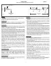
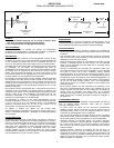
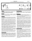
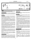
Catheter Placement and Imaging
With the PIM image "OFF" and using fluoroscopy, advance the imaging
catheter over the guide wire until the distal marker crosses a minimum of 3 cm
beyond the region of interest in the vessel/lesion.
Keeping the catheter body and guidewire fixed, turn PIM image "ON" and
retract the imaging core slowly along its 150 mm travel, imaging any region of
interest.
Note: Always turn the PIM image "OFF" before advancing the imaging core
within the catheter.
When finished, stop imaging by pressing the IMAGE button on the PIM, in
manual mode, advance the imaging core to its most distal position. Maintain
the position of the wire and remove the catheter.
Troubleshooting
If your system menu does not include "Revolution Catheters", contact your
Volcano Corporation representative before proceeding. If the images fade
during use, flush the catheter with heparinized saline. If shadowed areas
persist after flushing in situ, the distal lumen or catheter body may contain air
bubbles.
STORAGE AND HANDLING:
Products should be stored in a dry place with the temperature not exceeding
54 degrees Celsius (54˚ C) in their original cardboard box.
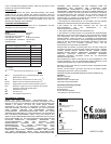
PRODUCT SPECIFICATIONS:
Model Revolution
Catalog number 89000
Crossing profile at transducer 3.2F
Maximum guide wire 0.014” (0.36 mm)
Minimum guide catheter 6F (1.63 mm)
Usable length 135 cm
Uncertainty
* +/- 29.1%
** +/- 14.6%
TI: Thermal Index defined as TI = W
01x1
f
c
210
W
01x1
: Bounded-square Output (mW)
f
c
: Center Frequency (MHz)
MI: Mechanical Index defined as MI= Pr.3/(f
c
1/2
)
I
SPPA.3
: Derated Intensity, Spatial Peak Pulse Average (W/cm
2
)
I
SPTA.3
: Derated Intensity, Spatial Peak Temporal Average (mW/cm
2
)
Pr.3: Derated Peak Negative Pressure at a location of the maximum
derated pulse intensity integral (MPa)
W
0
: Total Power (mW)
PD: Pulse Duration (μs)
PRF: Pulse Repetition Frequency (Hz)
Acoustic Output Parameter B-Mode
I
SPTA.3
(mW/cm
2
)* 70.778
I
SPPA.3
(W/cm
2
)* 95.533
Pr.3 (MPa)** 1.901
PD (μs) 0.048
PRF (Hz) 15360
Center Freq (MHz) 42.3
MI** 0.281
TI* 0.010