


Using Q1 menus
DN01145897 © Nokia Corporation 111 (128)
Issue 2-0 en Nokia Proprietary and Confidential
• BER alarm limit (6,4, port #,3,7)
The bit error rate (BER) alarm limit of the G.704/2M port can be checked
and changed using this menu. The BER alarm limit can be either 10
-3
(E-
3) or 10
-6
(E-6). Alarms can only appear if the frame format is either one of
the CRC-4 alternatives.
• BER alarm severity (6,4, port #,3,8)
This menu allows you to view and change the value set to the BER alarm
severity. Alarms can only appear if the frame format is either one of the
CRC-4 alternatives.
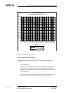
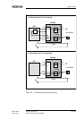
X.21-type interface settings (6,4, port #,3)
The X.21 adapter is installed in the port.
The menu (see Figure 67) allows you to check the current states of DTE circuits
and possible changes occurred during the last 15 minutes.
• Circuit C (6,4, port #,3,1)
The options of the submenu are:
- to display the use of circuit C
- not to use circuit C (Not in use)
- to select circuit C to control circuit I at the remote end by using ITU-
T V.13 signalling (Simulated carrier).
- Circuit I (6,4, port #,3,2)
There are two optional alternatives:
- to make circuit I follow the state of line synchronisation.
- to set circuit I to follow simulated carrier signalling (V.13).
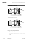
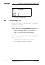
G.703/64k-type interface settings (6,4, port #,3)
• Interface mode (6,4, port #,3,2)
The interface mode can be codirectional or contradirectional (see Figure
68). In the contradirectional mode, you need to select the internal timing
source.
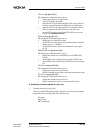
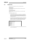
DTE interface (if) alarm (6,4, port #,5)
The Q1 DTE alarm handling can be enabled or disabled (see Figure 64). If it is
enabled, all DTE alarms of the port in question are transmitted to Q1
management. If the option Q1 alarms disabled is selected, DTE alarms are not
forwarded to Q1 management.