Data Network Terminal Single-port and Multiport Operating Instructions
38 (128) © Nokia Corporation DN01145897
Nokia Proprietary and Confidential Issue2-0en
Caution
5.9 Completing the installation
5.9.1 Verifying the installation
To verify that you have installed DNT2Mi correctly:
1. Switch the power to DNT2Mi with the power switch on the rear panel.
2. Check that the green LED (PWR) lights up on the front panel.
Do not cover DNT2Mi. The air inlets and outlets must be unobstructed to
maintain proper circulation of air.
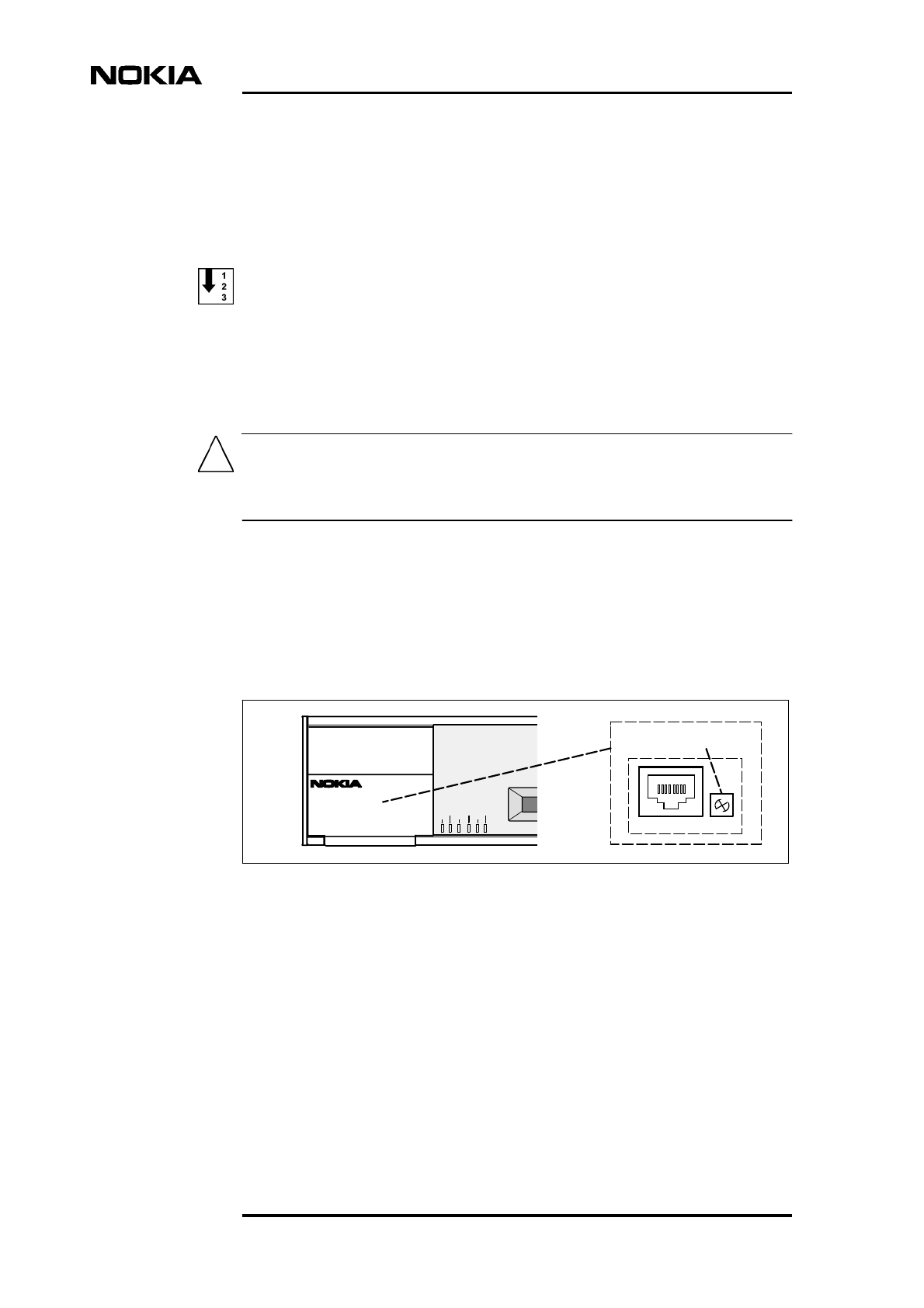
5.9.2 Adjusting the LCD display
The LCD adjustment (see Figure 25) may be necessary if the viewing angle
differs from the normal table-top viewing angle, which is the case, for example in
a wall mounting. Adjust the contrast with a small crosshead screwdriver.
Figure 25. Adjusting LCD contrast
5.9.3 Recommended actions after the installation
After the installation, we recommend you to:
• Label DNT2Mi unit(s) and cables according to your installation plan to
help future maintenance operations.
• Clean the site after installation. Recycle any applicable material.
OK
DNT2M
DTRDSR
DCDRTSCTS
STATUS
PWR TEST
P1
P2
P3
18
LCD-Contrast Adjuster


