


Data Network Terminal Single-port and Multiport Operating Instructions
58 (128) © Nokia Corporation DN01145897
Nokia Proprietary and Confidential Issue2-0en
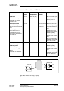
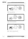
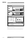
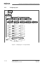
Figure 34. Front panel functions
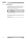
The following information is useful to know when working with the menus:
Request to Send
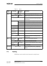
PWR
STATUS
Power on
Function
DTR
DSR
DCD
RTS
CTS
Data Terminal Ready
Data Set Ready
Line Signal Detector
Clear to Send
108
107
109
105
106
LED
The states of these signals are shown
Test on
Active data
in port 1, 2 or 3
Colour
Green
Red
Red
Green
TEST
P1, P2, P3
=
OFF
=
ON
State of signal:
=
DTE signal active during
INTERFACE SIGNALS
Display
(blinking)
=
DTE signal inactive during
in the Port display of the Monitoring
menu.
the last 15 minutes
the last 15 minutes
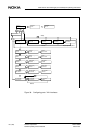
LED INDICATORS
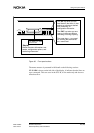
OK EXIT
DTR DSR DCD RTS CTS
STATUS
PWR TEST
P1
P2
P3
Multiport DNT2Mi
Single-port DNT2Mi
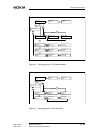
OK EXIT
DTR DSR DCD RTS CTS
STATUS
PWR TEST
PORT
DNT2Mi
DNT2Mi
A
la
r
m