


Maintaining DNT2Mi
DN01145897 © Nokia Corporation 53 (128)
Issue 2-0 en Nokia Proprietary and Confidential
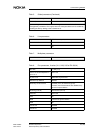
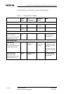
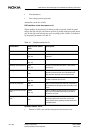
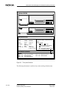
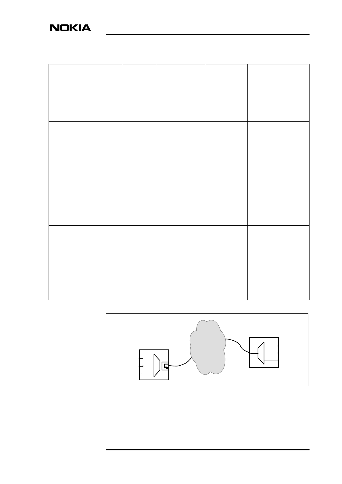
Figure 28. Network test loop (all ports)
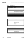
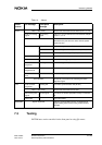
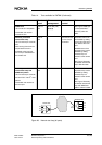
PRBS tests
ITU-T V.52 2
9
-1 test pattern
Transmitter and receiver
towards the line.
Port TR
test
Tx-Rx test (TR)
(5,2,#,4)
See Figure “PRBS (2
9
-
1) test (transmitter /
receiver)” after this
table.
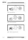
Remotely controlled
network test loop
ITU-T X.150 loop 2 at remote
end
Data coming from the line is
looped back to the line.
Activated at the local port
and a loop is established at
the remote end.
Port RL
test
V.xx Circuit 140
or X.21 loop 2
command
Automatic control can
be disabled by setting
circuit 140 in the ‘Not in
use’ state at the local
port.
Establishment of the
requested loop can be
disabled by setting
“Remote loop not
allowed” at the remote
end.
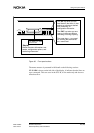
See Figure “Remotely
controlled network test
loop” after this table.
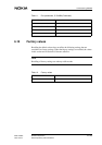
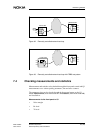
Remotely controlled
network test loop with
PRBS test pattern
ITU-T X.150 loop 2 at remote
end and ITU-T V.52 2
9
-1 test
pattern
Transmitter and receiver at
the local port.
Port RLTR
test
Establishment of the
requested loop can be
disabled by setting
“Remote loop not
allowed” at the remote
end.
See Figure “Remotely
controlled network test
loop with PRBS test
pattern” after this table.
Table 14. Tests available for DNT2Mi (Continued)
Front
panel
Q1
management
Automatic
control
Note
DTE
PORT 2
DTE
DTE
REMOTE DNT
PORT 1
PORT 2
DTE
PORT 3
DTE
LOCAL DNT
LINE
BLOCK
PORT 1
PORT 3
DTE