


Data Network Terminal Single-port and Multiport Operating Instructions
90 (128) © Nokia Corporation DN01145897
Nokia Proprietary and Confidential Issue2-0en
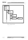
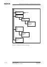
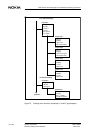
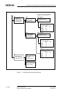
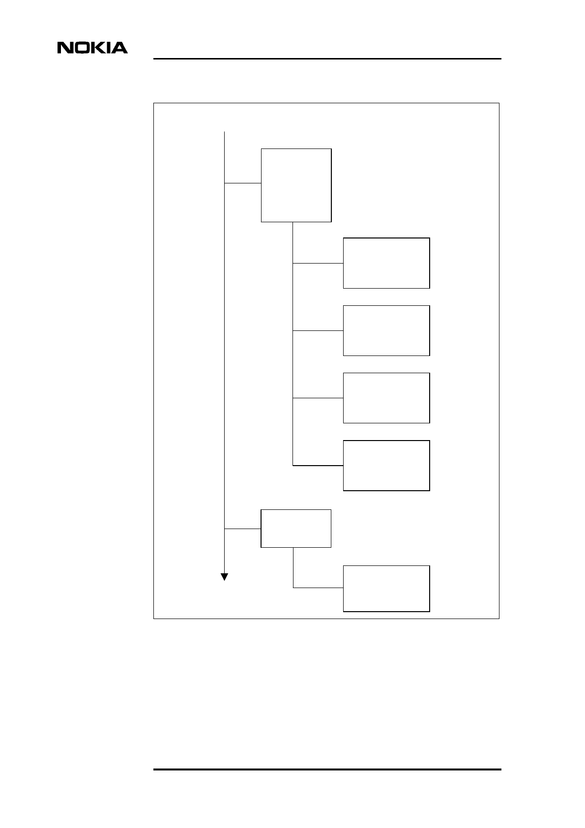
Figure 67. Settings menu structure (continued), X- and VF-type adapters
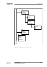
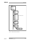
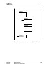
6,4,port#,3
Circuit C:
0 Display
1 Not in use
2 Simulated carrier
Circuit I:
0 Display
1 Follows line sync
2 Simulated carrier
RL request:
0 Display
1 In use
2 Not in use
LL request:
0 Display
1 In use
2 Not in use
6,4,port #,3,1
6,4,port #,3,2
6,4,port #,3,3
6,4,port #,3,4
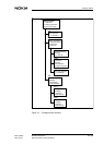
X.21 interface settings:
X.21 type DTE:
0 Display
1 Circuit C
2 Circuit I
3 RL request
4 LL request
6,4,port#,3
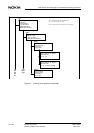
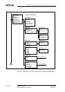
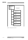
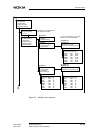
VF type DTE:
0 Display
1 Input level
6,4,port#,3
Give input level:
0 Display
-22.0...-7.0 dBm
(0.5 dBm resolution)
6,4,port#,3,1
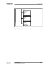
VF Interface settings: